|
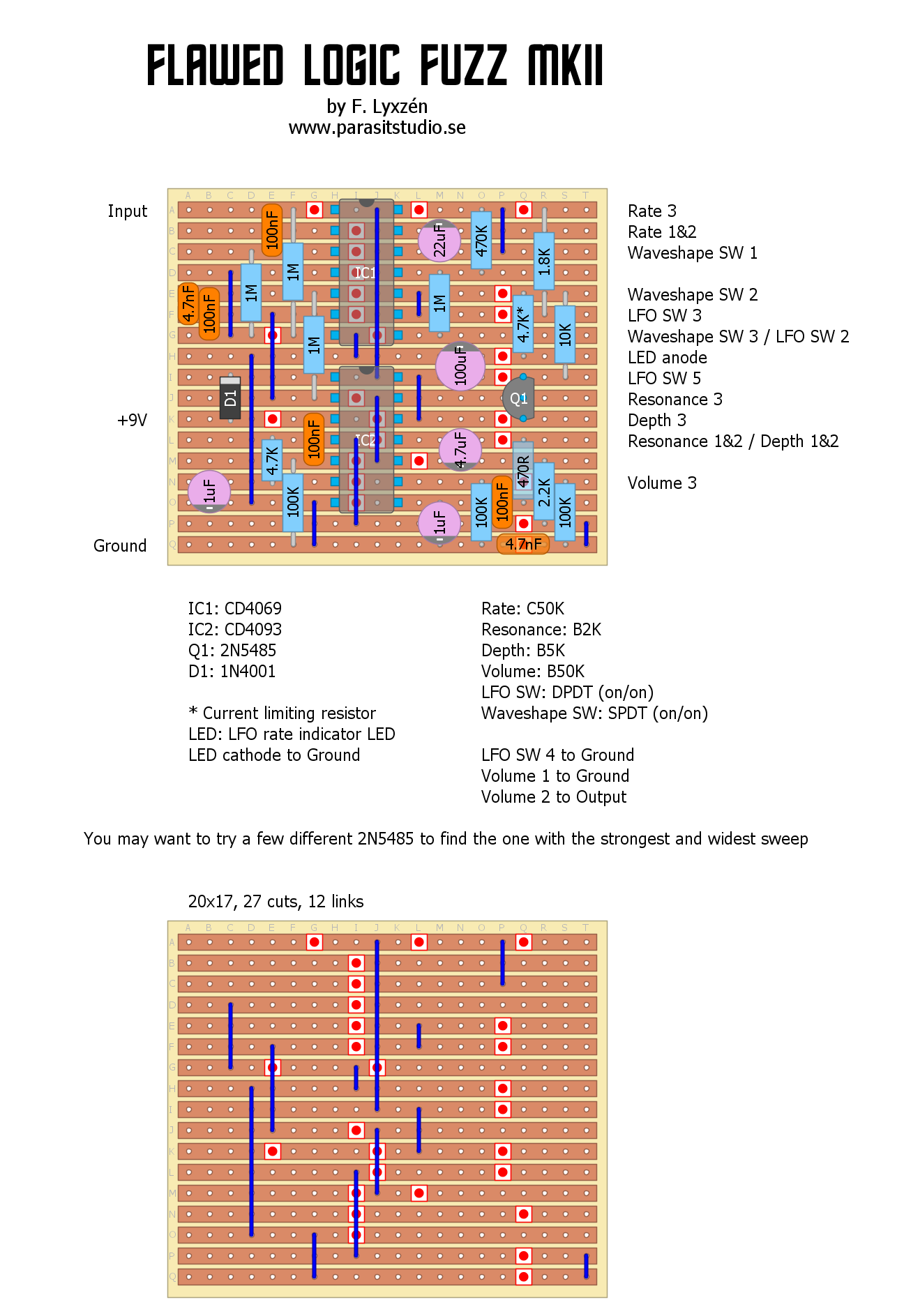
I'm proud to present the Flawed Logic Fuzz MKII. The original Flawed Logic Fuzz was a fun circuit, but it suffered from too short sustain and the modulation part could have been better. The MKII is improved in these areas and also has a couple of new features such as a depth control and a waveshape switch for the LFO. I'm especially happy with the new triangle LFO waveshape that makes a sort of phaser'ish sound. This circuit is made up of a square wave fuzz followed by two gated oscillators in series (NAND gates). The LFO modulates the frequency of the second oscillator. This produces a very synthy, throaty sound that is unlike any other fuzz. I hope you like it. :) PCB avaliable in the shop
19 Comments
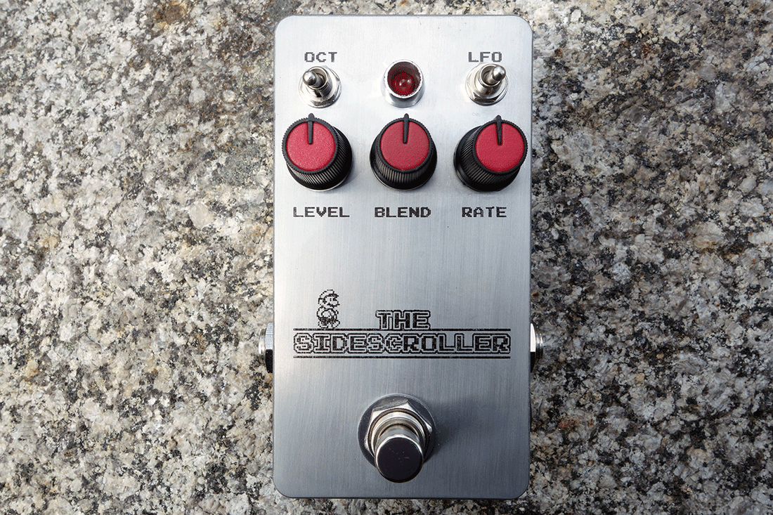
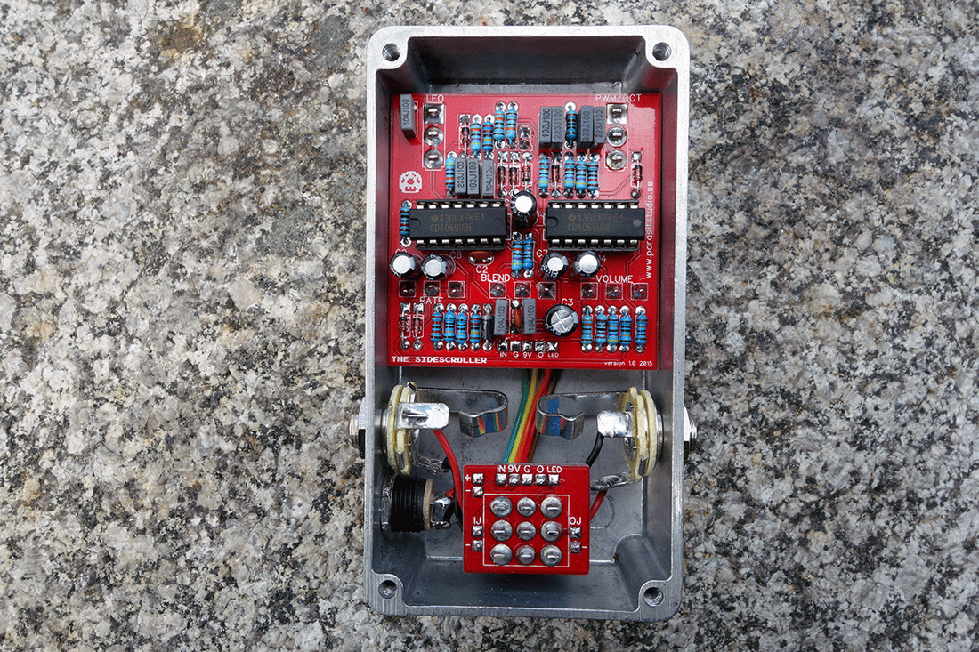
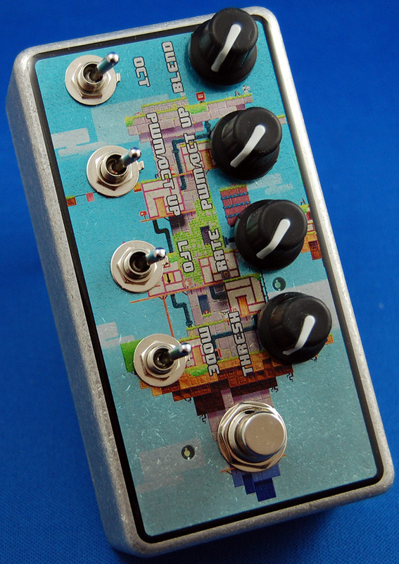
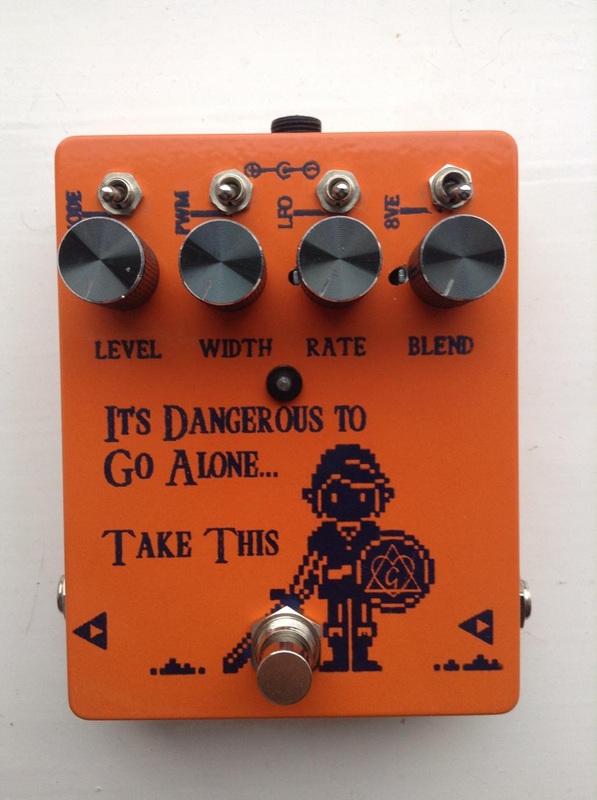
Here is a new original design - The Sidescroller Fuzz. It started out as a derivative of the Silver Fox Octaver, but it turned out quite different. Soundwise It's basically "the arcadiator light" since It also does octave down, octave up and pulse width modulation. Compared to The Arcadiator it has tighter controls, fits in a 1590B and has a unique feature: An LFO to modulate the Pulse Width. All this only using a couple of CD4069 inverter chips. :)
PCB avaliable in the shop
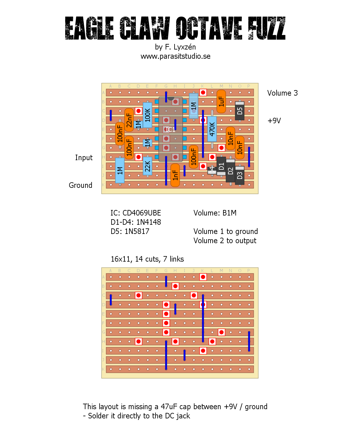
Here is a new original design - The Eagle Claw octave fuzz
It's a very simple CMOS based circuit with a full wave rectifier for the octave up. Makes a fairly strong octave, but usual caveats apply for best results - humbuckers, neck pickup and tone rolled off. For fun I threw together a short demo song for this one insted of a regular soundclip. This it how it sounds in context with drums and bass (I mixed the bass low). It has some minor eq for touch-up.
My completed pedal. It turned out ok, but the etch could have been alittle better. My toner is running out so the transfer wasn't that good to start with.
For this build I used a prototype dual layer PCB from OSH Park. PCB's will be avaliable for purchase when I get my webshop up and running. The last image shows the microphone placement in the demo. I only used one microphone on the drums. Why make it more complicated then it has to be? :)
The name is after the kung fu style. Here is one of my favourite movies that features the eagle claw style.
PCB avaliable in the shop
Here is my taken on the Analog Bit Crusher by Colin Raffel. It's a cool circuit that uses sample and hold to degrade the signal. I guess a more accurate description would be aliaser / sample rate reducer. I replaced the oscillator with a better one that has a wider range and an additional pulse width control. I also added a much needed gate for the carrier oscillator - a envelope follower that turns off the oscillator when not playing. No more carrier bleedthrough. :) The controls are: Resolution - controls the pulse width of the oscillator. Wider pulses lets more clean signal through Sample rate - control the frequency of the oscillator Gate (trimmer) - this sets the gate threshold for the oscillator in relation to the input signal I etched the enclosure for this one. I'm very happy with the result. :) This tutorial is very good: http://diy-guitar-effects.tumblr.com/etching The name and text on the enclosure comes from the lyrics from this song. But I bet you knew that already, otherwise - shame on you! :o) PCB avaliable in the shop
edit 2016-03-08: Added a demo video
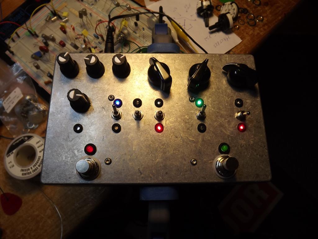
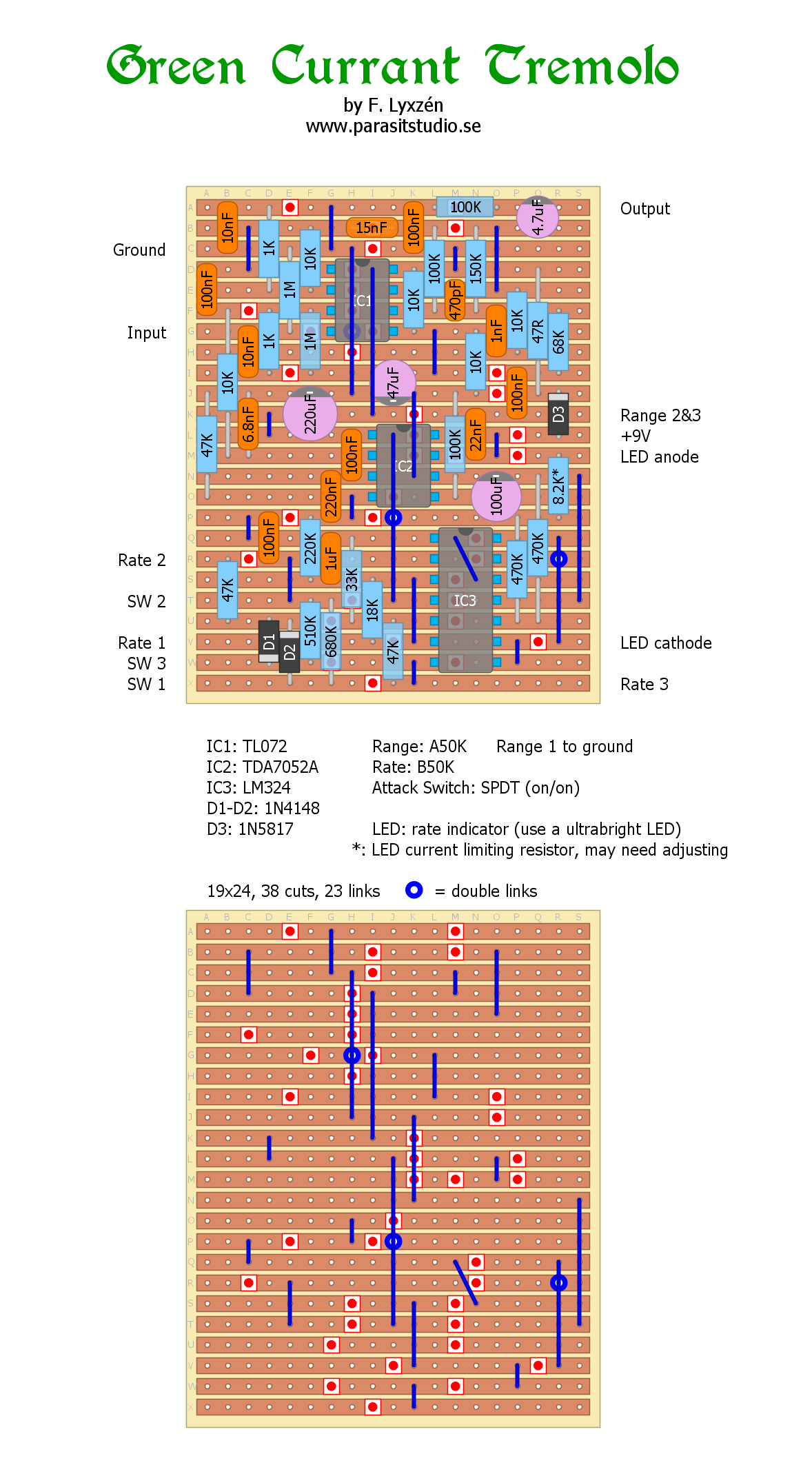
Here is a new original design. I'm very happy with how this one turned out. :) It's a very percussive tremolo based around the TDA7052A amplifier chip.
It continues with the idea I had when I designed the Black Current Vibrato, that two signals out of phase is summed together. One side is static while the other side is being modulated and filtered to leave some frequencies unaffected. This results in what sounds almost like a light phaser and vibrato'ish effect. So in a sense this is a continuation of the Black Current Vibrato (hence the play on words) but without the stutter mode and otherwise improved in every way; more neutral sounding, less noisy, more control, more versatile LFO and no ticking noise.
The controls are:
Rate - Controls the speed of the LFO Range - Controls the range of freqencies effected by the modulation. Attack switch - Sets the waveshape to hard (sawtooth) or soft (ramp). I will post a video-demo later, but not until I have boxed this one using a fabbed PCB (just because it will be alot smaller and easier to fit inside a 1590B - the vero is verified and perfectly fine). So that might take a while.
PCB avaliable in the shop
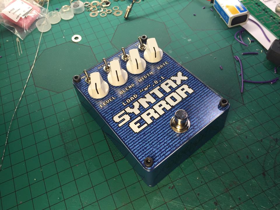
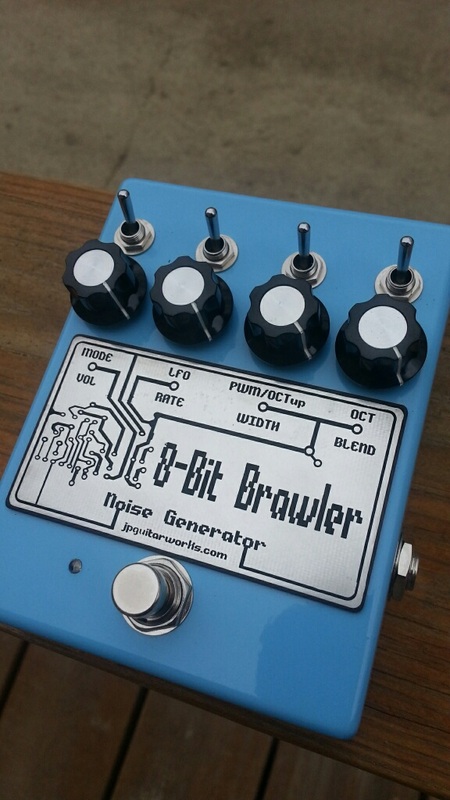
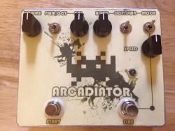
For me DIY is about sharing info and knowledge and this blog is my way of contributing to the DIY community. I love seeing other people build by humble creations. Here is a few builds done by other people :) I hope it's alright that I snatched these pictures of the web. With enough pictures I might do a gallery section on the blog, so please send me your pictures if you got any and want me to share. :) On a more serious sidenote.. There are a couple of unwritten rules within the DIY scene. 1. Never use DIY schematics or layouts for profit without permission. I think it's ok to build a couple of pedals to sell to friends, but nothing more. 2. Always give credit to the original creator and never take credit for someone elses work. I always give credit for every vero layout I make ect. I only ask that you do the same for my stuff and respect these rules. Thank you! Update 2015-03-29: I updated the vero layout. It's exactly the same, but I made the offboard wiring instructions clearer to avoid confusion. It's 100% verified. The Arcadiator, a video-game'ish fuzz. Usually I'm trying to keep the controls simple. but for this design I really wanted to max out the possible sounds from the chips so it ended up with many switches and knobs. It does glitchy square-wave fuzz, pulse width modulation (similar to Tim Escobedo's PWM), octave down and modulation that alternates beween two octaves. It basically does everything that the Silver Fox Octaver does, and alot more. I hope you like it :) The toner transfer didn't turn out good for this build (but hey, it's DIY right :)) and I should have used a lower value resistor for the LED. It's blinking when the LFO is engaged, but you can hardly see it. CONTROLS PWM switch - this toggles between 'pwm' or 'octave up' WIDTH pot - this controls either the width of the square wave (pwm) or the intensity of the octave up BLEND pot - mixes between 'either PWM or Octave up' and the 'Octave Down' OCTAVE switch - This toggles between one or two octaves down MODE switch - this turns the Octave down on or off (except when the LFO is on) MODULATION LFO switch - turns on/off the modulation that is alternating between one or two octaves down, or: MODE switch - Toggles between either one or two octaves down or just one octave down and unison or a choppy tremolo of the octave down (depending on how the mix is set) RATE and LEVEL doesn't need explaining :)
It's a Idiotbox Blowerbox bass Distortion and a Dead Astronaut Chasm Reverb. I really like how they both turned out - recommended builds. You can buy the Chasm Reverb PCB from http://deadastronaut.wix.com
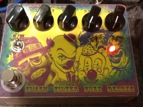
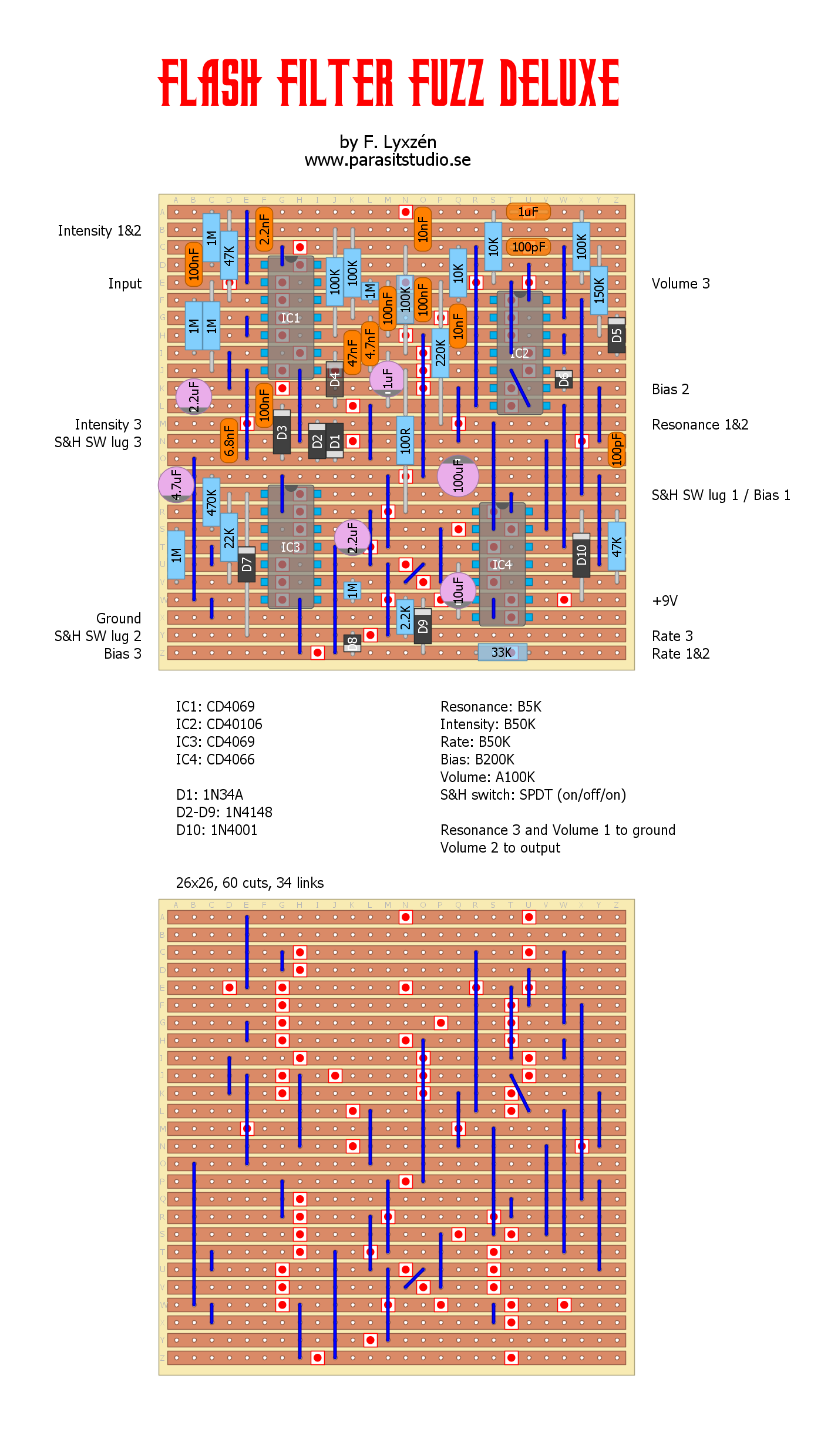
Update 2015-03-29: I added a vero layout of the deluxe version. Thanks to Synsound at the tagboardeffects forum for verifying! Here is a new original design. :) The Flash Filter Fuzz is a inverter-based squarewave fuzz with a resonant highpass filter and sample & hold modulation. I made layouts for two different versions, a standard and "deluxe" version. Here is a demo-video of the deluxe version (modulation starts at about 4:00) I found this pedal kinda hard to demo, but you should get the idea. :) The controls are as follows: Intensity: This controls the strenght of the resonant peak. Turn it up and it will oscillate. Resonance: This controls the frequency of the filter cutoff/peak. Rate: Controls the speed of the sample and hold modulation. Bias: This controls the depth and range of the sample and hold modulation. It was originally intended as a internal trimpot, but I found it very useful as an external pot. Ultimatly it should been two different pots to control both range and depth, so the 200K pot is a bit of a compromise, hence the not so perfect sweeping action. S&H switch: This is a on/off/on switch that has 3 different modes; LFO disengaged, LFO free running and LFO gated by the guitar signal. With the LFO free running and the intensity turned up into oscillation the circuit turns into a synth/noisemaker thingy. :D Deluxe version layout and schematic:
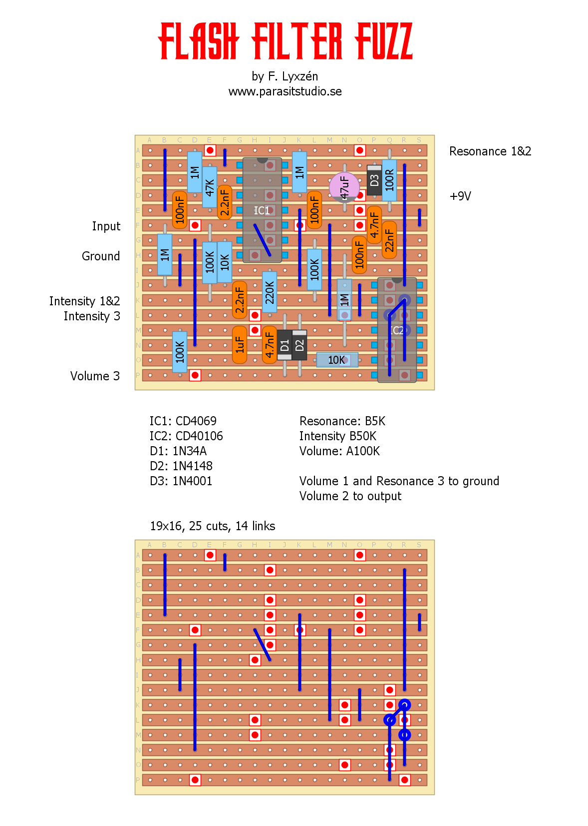
Standard version PCB and vero layouts: This version doesn't have the sample and hold modulation and is alot simpler to build. It's also tuned slightly different so that it doesn't oscillate with the intensity turned up.
Just a silly post... I'm working on a fuzz with a sample and hold modulated resonant filter. By accident I happened to connect two wires that wasn't supposed to be connected, the beatbox duck was born! This is just me goofing around and the finished pedal with sounds nothing like this. |
|||||||||||||||||||||||||||||||||||||||||||||||


