PARASIT STUDIO
  • DIY GUITAR EFFECTS
    • Original Effects
    • Building blog
    • DIY Gallery
    • Stripboard layouts
    • Articles
  • SHOP
  • BUILD DOCS
  • ABOUT

Flawed Logic Fuzz MKII

6/25/2015

19 Comments

 
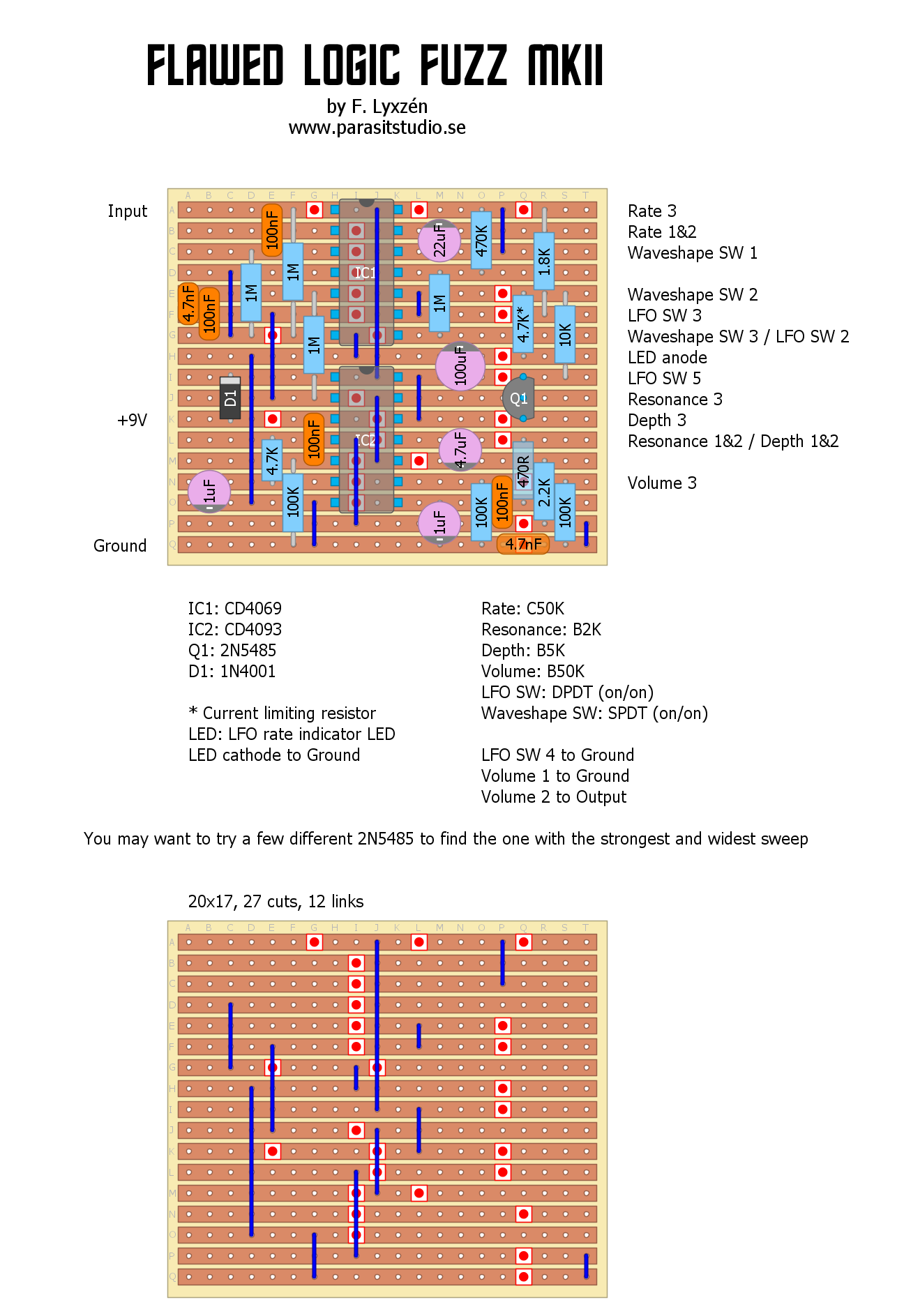
I'm proud to present the Flawed Logic Fuzz MKII.

The original Flawed Logic Fuzz was a fun circuit, but it suffered from too short sustain and the modulation part could have been better. The MKII is improved in these areas and also has a couple of new features such as a depth control and a waveshape switch for the LFO. I'm especially happy with the new triangle LFO waveshape that makes a sort of phaser'ish sound.

This circuit is made up of a square wave fuzz followed by two gated oscillators in series (NAND gates). The LFO modulates the frequency of the second oscillator. This produces a very synthy, throaty sound that is unlike any other fuzz. I hope you like it. :)
PCB avaliable in the shop
flawed_logic_mkii_vero.png
File Size: 165 kb
File Type: png
Download File

19 Comments
Synsound
6/28/2015 05:39:53 am

I've been on the lookout to see this!
Just went through my parts to make sure I had everything. I should have her done in a couple of days. Keep up the good work.
BTW The site is looking great.

Reply
Fredrik Lyxzén link
6/28/2015 06:04:30 pm

Thank :)
Let me know how you build goes. Cheers, Fredrik

Reply
anders
7/1/2015 04:02:50 am

Hi! Just built this monster. After some hassle with the LFO switch I got it working; as you states a throaty brutal fuzz with a quite flexible LFO section. I really dig the triangle wave mode...is there a way to slow the speed of the modulation, I'm craving for long filter/phaser sweeps. :-)

Cheers and thanks again for your work

Reply
Fredrik Lyxzén link
7/1/2015 06:17:55 am

Thanks for the build report. :)
You can try a higher value for the rate pot, 100K or higher, although the sweep might be a bit strange and have most of the action in the end of the turn. Otherwise you can experiment with changing the LFO timing cap. It's the 22uF capacitor. The 1.8K resistor sets the max speed, so with a larger timing cap you might want to reduce the resistor to maintain the faster speeds aswell.
Cheers
/ Fredrik

Reply
John
7/17/2015 11:38:14 am

The build instructions say the resistor is 2N5485 is one place and 2N5458 in another. Which one is it supposed to be? Would a 2N5457 or J201 work as well? Thanks

Reply
Fredrik Lyxzén link
7/17/2015 06:39:23 pm

Hi John,
The 2N5485 is the correct one. I will correct the build instructions. Thanks for pointing out the error. A J201 or 2N5457 will work, but the range and sweep will not be nearly as good. At least that was my experience when testing different jfets for this circuit.
cheers / Fredrik

Reply
Carsten
9/29/2015 10:03:58 am

Great Pedals.

Reply
Fredrik Lyxzén link
10/6/2015 09:42:59 am

Thanks! :)

Reply
Shane
12/8/2015 07:00:53 am

Built the PCB version of this and am only getting farty noises out of it.
Any trouble shooting tips that you recommend I start with?
Thanks

Reply
Fredrik Lyxzén link
12/29/2015 03:27:58 am

Hi Shane,
Sorry. I had totally missed your post. Could you post IC voltages and high resolution pictures of your board and let me have a look? There's a tech help thread in the madbean forum here: http://www.madbeanpedals.com/forum/index.php?topic=22962.0
If you post there, more people can help out aswell. Cheers / Fredrik

Reply
Aisha
7/22/2016 06:46:14 pm

Hi! I'm almost finished with the vero version of this. Could you tell me, do poles 1 and 5 of the LFO switch connect anywhere? Also, I'm using CD4069UBE and CD4093BE. Are those correct?

Thank you!

Reply
Fredrik Lyxzén link
4/12/2017 04:16:09 am

Hi Aisha
Just noticed your comment. For some reason I never got an email notification about it, so I missed it. Sorry. It's probably too late to answer this now, but I will answer anyway. :)
The CMOS chips are the correct ones. The LFO switch pin 1 doesn't connect anywhere, but pin 5 connects to row 9 on the right side of the board as shown.
/ Fredrik

Reply
Wizombie
3/31/2017 01:18:03 pm

Please help made vero of this and after 3 builds of this it's still not working it's actually very upsetting cause the demo vid is teasing me

Reply
Fredrik Lyxzén link
4/12/2017 04:17:45 am

Can you discribe how it's not working? I can't help without more info.
Cheers / Fredrik

Reply
Wizombie
4/12/2017 02:04:01 pm

it just squels and oscilates seeems to have no input signal or output hang on i think it may be due to incorrect tran would that be an explanation?

Wizombie
4/12/2017 04:22:41 pm

got the right transistor but still nothing man any chance you could email me a crude wiring layout im lost as to what ive done wrong

Fredrik Lyxzén link
5/6/2017 03:46:21 am

The transistor isn't crucial. It will work without it, but without the modulation/LFO section.

First step when troubleshooting, make sure you have all your grounds connected (input and output jack sleeves, DC jack negative and ground on the veroboard), then use a multimeter to confirm that the chips have ground on pin 7 (use the continuety mode that beeps when putting the probes together - one probe connected to ground somewhere and probe with the pins with the other probe).

Then set your multimeter to DC current mode and make sure that the chips have around 9 volts to pins 14 (top right pins)

Lasty, make an audio probe (just a piece of wire in series with a 100nF capacitor connected to a output jack tip, with the output jack sleeve connected to DC jack negative and Ground on the board) connected to an amp (at very low volume), and probe the circuit signalpath to hear where the signal goes away:

* Pin 4 of IC1 if the output of the first gainstage. Here you should hear a amplifier and pretty distorted signal.
* Pin 6 of IC1 is the output of the second gainstage. Here you should hear an even louder and much more distorted signal.

* Pin3 of IC2 is the output from the schmitt trigger stage. Here you should a gated sounding square wave fuzz
* Pin 10 and 13 of IC is the output from the first oscillator stage. Here you should hear a very synthy squarewave fuzz

I hope that helps. Cheers / Fredrik
Sorry for the slow reply

Reply
David List
4/29/2018 03:28:28 pm

Hi Fredrik, are n´t you selling this item anymore? Greetings from Hamburg, David

Reply
Fredrik Lyxzén link
4/30/2018 01:40:15 am

Hi David,
No, I discontinued this PCB a while back because I wasn't 100% satisfied with the design, but I might re-release it as an updated version in the future. Cheers / Fredrik

Reply


Leave a Reply.

  • DIY GUITAR EFFECTS
    • Original Effects
    • Building blog
    • DIY Gallery
    • Stripboard layouts
    • Articles
  • SHOP
  • BUILD DOCS
  • ABOUT