PARASIT STUDIO
  • DIY GUITAR EFFECTS
    • Original Effects
    • Building blog
    • DIY Gallery
    • Stripboard layouts
    • Articles
  • SHOP
  • BUILD DOCS
  • DISTRIBUTORS
  • ABOUT

0415 Guitar Synth

10/9/2015

42 Comments

 
Update 2015-10-09
The new 0415 Guitar Synth is done and PCB's are now avaliable in the shop! :)
​A verified vero layout added to the bottom of this post.


This is a simple but fun pedal that transforms the signal into a square wave, up to five octaves apart: one or two octaves up can be mixed with one or two octaves down for super synthy sounds.

What makes this special is that the octave up part is based on a frequency controlled oscillator so it doesn't scramble chords like usual octave circuit and it tracks well over the entire fretboard. Compared to the Arcadiator it sounds less like a fuzz and more like a pure synth. It can be very controlled, but also make superglitchy sounds.
Picture
Populated prototype PCB
In case you are wondering about the name, it has nothing to do with the CD4015 chip used. It's the birthday of my dog. :)
Picture
One of my dogs, Wookie (a bearded collie)
I made a quick recording of a cheesy "blues". The settings on both tracks were one octave down and two octaves up.
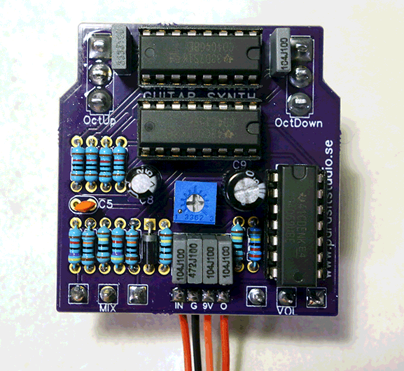
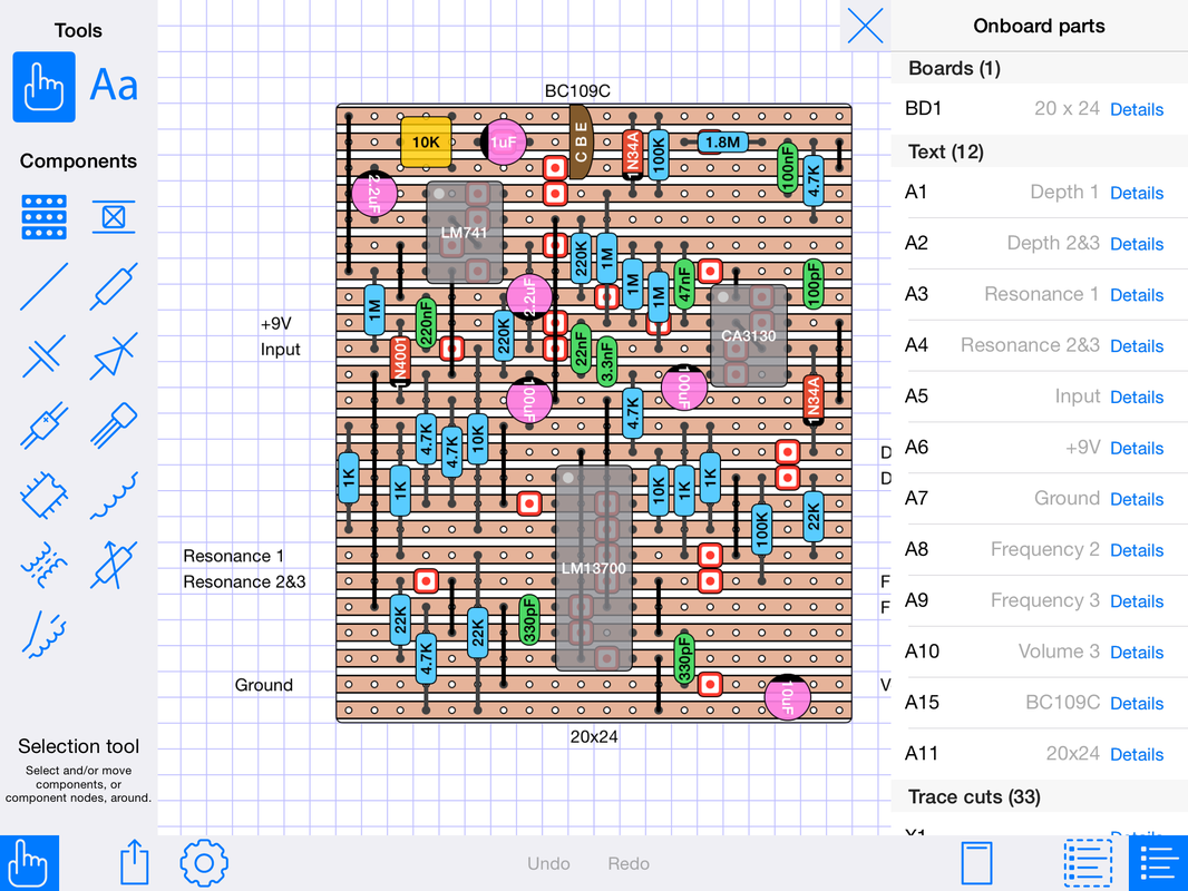
This circuit is basically a light version of a upcoming pedal that will be called "into the Unknown Guitar Synthesizer". It's based around the same chips, but it will be a monster with 8 pots and 3 switches... More about that one later.

0415 guitar synth vero.png
File Size: 282 kb
File Type: png
Download File

42 Comments

StripboardCAD 1.1 mini review

9/8/2015

0 Comments

 
Since a couple of years back I've been doing all my vero layouts using DIY Layout Creator 3.27.0. It's a good and simple freeware program.

However, I'm lazy so I like to sit in the sofa or lay in bed working on layouts with my ipad. Up until now I have used a streaming app (splashtop) for my ipad to remote control my computer. It has worked ok, but far from a perfect solution. So I was very excited when I heard that Harald Sabro was doing a dedicated stripboard app.

After using it for a while to make a few layouts, here are my thoughts: It's very intuitive and easy work with. I started making my first layout just minutes after downloading the app. The GUI looks nice and it's obvious that Harald has spent alot of thought into the design. I was worried that the touchscreen interface would be a problem, but it works great. Even small trace cuts are easy to move around without accidentally moving the wrong component. The first version was missing a feature to display the values directly on the components (which I prefer) but that got added in version 1.1. I have encountered one small bug when the app freezes up for a while when deleting several components in a row, but overall it runs great without any crashes and I expect any bugs to be fixed in future updates. Compared to DIY Layout Creator (which can do alot more than just stripboard layouts) it lacks features such as being able to resize components ect, but for my needs it's perfect. Highly recommended and worth every penny!
StripboardCAD is limited to iOS and costs $9,99 in the appstore.
www.sabrotone.com
0 Comments

New family member

9/1/2015

2 Comments

 
This post is alittle more personal... But I just had to share this. :)

This little fellow to the right is moving in with us next week.
His name is Silver Fox, but we'll call him Lee (after Bruce).

Funny thing is that when the kennel owner (a friend) needed a theme for the names, she decided to name them after my guitar effects! :D So this little bunch of puppies are named: Arcadiator, Sonic Reducer, Stepping Stone, Raygun Youth, Sidescroller and Silver Fox.

These are the registered birth names, so what their owners will call them later is up to them. But still... So I couldn't resist keeping one of them, the only black dog.
Picture
2 Comments

Arcadiator videos

9/1/2015

3 Comments

 
Here are a few Arcadiator videos from various people on youtube. :)
It's fun to see these pop up and I'm greatful and honored for all the work people put into these videos. Thanks!
3 Comments

Repair day

9/1/2015

0 Comments

 
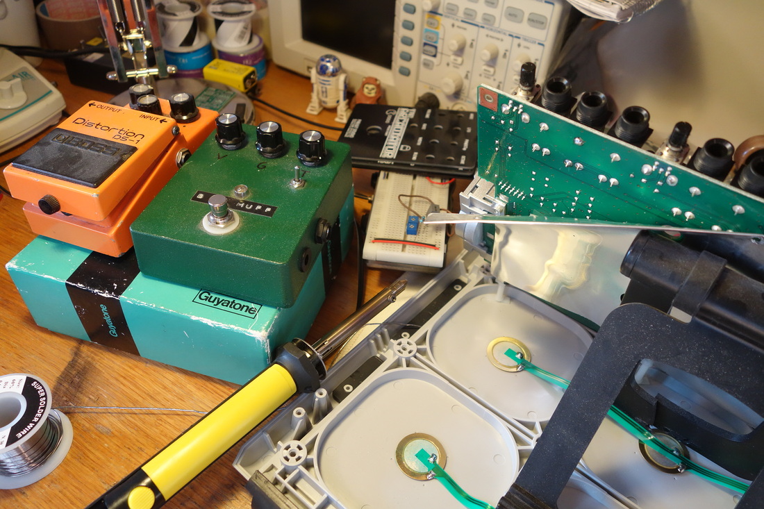
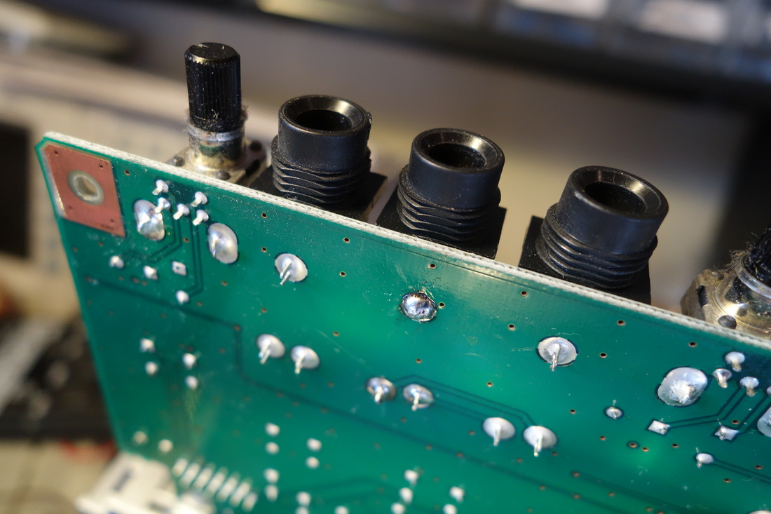
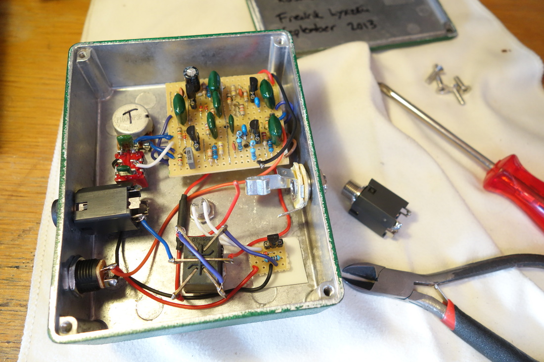
You started building stompboxes and now everyone think that you are a master at fixing broken electronics... Here are a few things that people has asked me to repair. I usually hate troubleshooting, but these were surprisingly easy fixes.
Here's a few things that needed fixing. First out is a Roland PAD. It was the hardest of the bunch since taking it apart and putting it together takes a while.
The Roland drumpad had a broken output jack. I desoldered the jack, took it apart and managed to fixade the loose part inside the jack with a small dab of solder.
A Big Muff I built I couple of years ago. The jacks were too loose for the owner, so I simply exchanged the jacks. Easy peasy.
A "broken" DS1. The only problem was a broken battery clip. I exchanged it for a new one.
A really nice looking old chorus in great condition that only passes clean signal after plugging in the wrong powersupply. Makes me think the MN3002 has gone bad. I'll order a new one to test if it solves the problem.
A pretty nice guitar found in a dumpster... Only the neck pickup gave any output. I simply reflowed the solder at the volume and tone pots and tadaaa.. It's working again. Nice free guitar. :)
0 Comments

CMOS workshop part 3 - octave down

8/24/2015

24 Comments

 
Picture
6. Octave down, Flip Flops and Latches
Lets have a look at a few different ways to create octave down using CMOS chips.

In all of the examples below something called a flip flop will do the frequency dividing. The flip flop/latch is one of the fundamental logic building blocks. It's used to store data and is how RAM memory in our computers works. One flip flop can store 1 bit of data, which means that it can hold a high or low state until we tell it otherwise. This can be very useful, for example when we want to use a momentary switch to turn something on or off until we press it again. Flip flops can also be used as oscillators, counters and much more.

But now let's focus on frequency dividing. What it does, to put it as simple as possible: Each time the clock (our input signal) goes high, the output changes state. Since the output only changes on the positive transitions and holds that state on the negative transitions we get exactly half the frequency at the output, like this:
Picture
Picture
Example of a basic S-R flip flop using NAND gates
Picture
Example of a flip flop latch
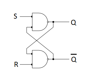
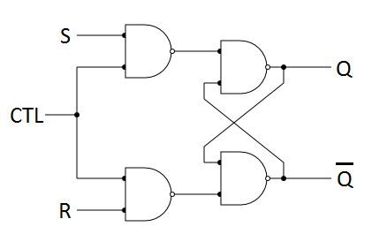
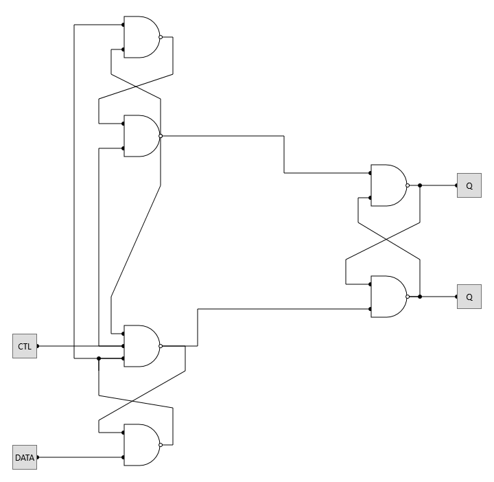
If you want to learn more about the logic math behind the flip flop, I recommend this video:
https://www.youtube.com/watch?v=PCT76PsDr6g

Pre-filtering
Making a octave down circuit with CMOS is easy since we are now working with 1's and 0's. Getting good tracking is harder, but there are a few simple measures we can take to get acceptable tracking. The first thing to keep in mind is that we can improve tracking significantly by using the neck pickup of the guitar and the treble rolled off. But we also need to add a lowpass filter after our schmitt trigger since it adds alot of high frequency content. There are many different lowpass filters we can use, varying in complexity, but for this article we'll use a simple passive RC filter.
Picture
RC lowpass filter
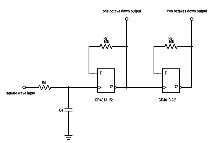
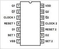
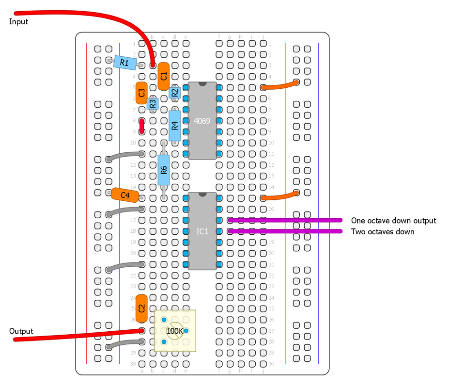
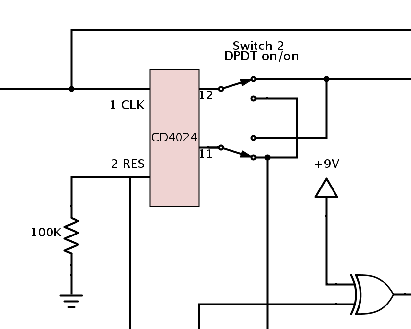
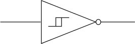
Here is a sound example of octave down with: 1. Bridge pickup, no filter 2. Bridge pickup with RC filter 3. Neck pickup with RC filter.

Let's get the breadboard ready!
We'll start out with the circuit we made in part two, then add the new section before the output capacitor. To keep it simple, the schematics will not show the "cmos'ifier" part or the output part. Lets add the RC filter first (R6/C4). 10K and 22nF-100nF is a good starting point. Then we'll add the octave down part.

No decoupling capacitor after the schmitt trigger is needed. CMOS chips are make to interface with each other directly so decoupling caps are rarley needed, except for linear amplifiers, filters or special schmitt trigger operations. It's very forgiving this way.

1. Dual D-Flip Flop (CD4013)
This chips is used in the MXR Blue Box, MadBean Lowrider, The Rocktave and many others.

This chip has two D-flip flops. The D prefix means that it changes output state on positive transitions only, exactly what we need. For two octaves down, we'll just put both flip flops of the chip in series so that the second flip flop will divide the output of the first flip flop.

  • Input goes to Clock
  • The NOT Q output (Q with a line) goes back to the data input (D) via a 10K resistor
  • Set and Reset goes to ground
  • Q or NOT Q goes to output. NOT Q is the inverted output
  • VCC to V+ and VSS to ground
Picture
CD4013 pinout

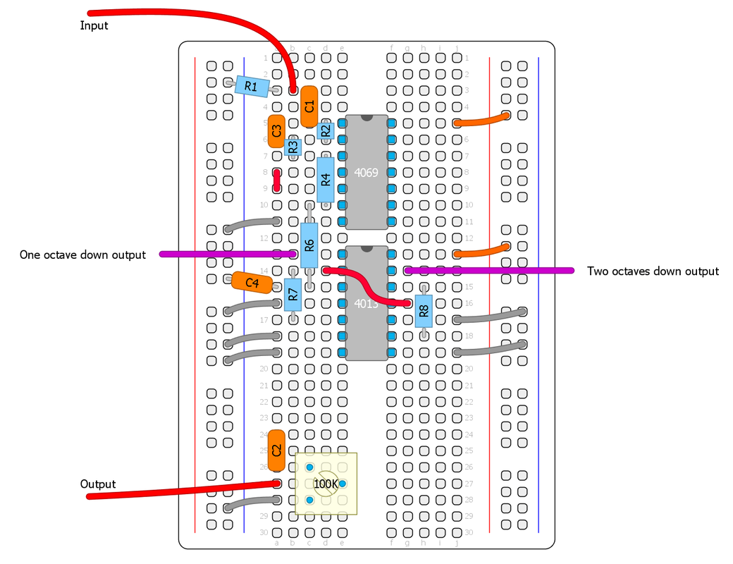
Output controls
You can use pots/trimmers as variable resistors or voltage dividers to have control over each octave or a switch to toggle between them, a blend pot/trimmer between straight square wave and octave down ect... Experiment with the controls that you want. Here are a few examples:

2. Binary Ripple Counter (CD4024)
This chip is what I used in the Arcadiator. it's very common in DIY synth stuff and it's also used in the Slacktave (by Slacker, the designer of the Echo Base) and the Bit Commander by Earthquaker Devices. It's very simple to use and require no extra external components.

The CD4024 chip is a counter that advances one count every time the clock changes from high to low. The first output is divided by two, and the next output divides the preceding output by two and so on, up to output 7 that has the input frequency divided by 128. This means that each output is one octave lower.

  • Input goes to Ø
  • Reset goes to ground
  • Q1 is the one octave down output
  • Q2 is the two octaves down output
  • VCC to V+ and VSS to ground
Picture
CD4024 pinout
Picture
Picture
Part of the Arcadiator schematic

3. NAND Gates (CD40106, CD4093)
Let's look at how it's possible to make a D-flip flop out of NAND gates.

As you can see, it requires many gates and even one 3-input gate, which means we have to use at least two chips. But remember that I mentioned that schmitt triggers can be configured to make NAND and NOR gates?

A schmitt trigger gate can be made into a multiple input NAND or NOR gate using 1N4148 diodes and a resistor, with as many inputs as we want. This is something I picked up from Ray Wilson, he calles it "mickey mouse logic". This makes the CD40106 a very versatile chip, and using this neat trick we can make a flip flop out of a single CD40106 chip.
Picture
"mickey mouse logic"
The same mickey mouse logic can be applied to the 2-input CD4093 schmitt trigger by first connecting both inputs together (which makes a NOT gate).

A good way to test these octave down circuits on the breadboard is to connect a LFO with a LED to the input and another LED at the output. That way we can easily see if it works. I tested the NAND schematic first with a freeware program called Logic Circuit just to make sure it would work, then I breadboarded it. This is the result.
For this video I used another CD40106 for the LFO. We'll cover LFO's in a later part. (Ignore the extra parts on my breadboard and the non decoupled inputs.. I cheated alittle to make it quickly...)
Picture
NAND equivalent of a D-flip flop
Picture
CD40106 flip flop schematic
Picture
Transistors bi-stable multivibrator (equivalent to a D-flip flop) from the Colorsound Octivider schematic
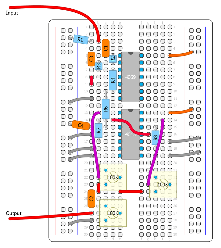
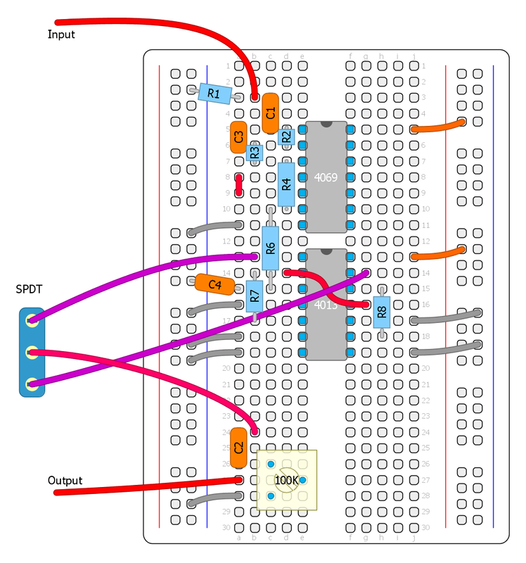
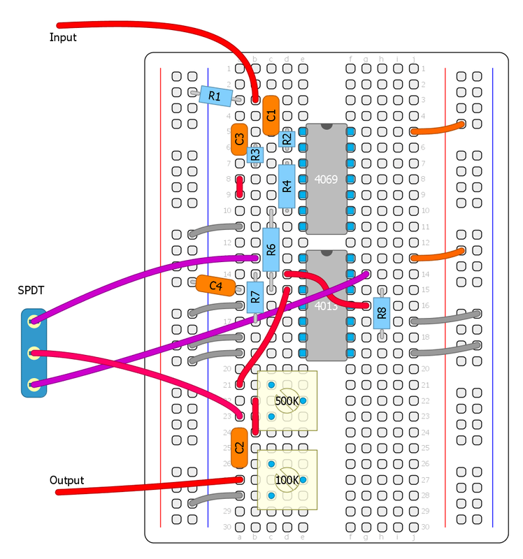
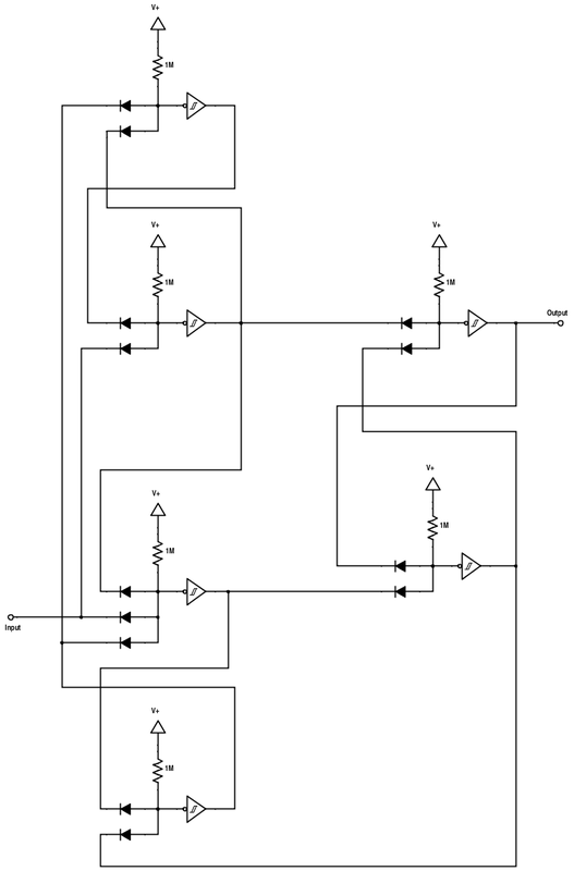
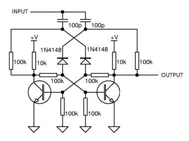
It works. :) I actually used this flip flop version for the sound example in the beginning of the post. This was very confusing to breadboard and I won't even try to make a breadboard diagram. It's not a very convenient method, unless you have a huge stash of schmitt triggers and diodes that you want to put to good use... I just wanted to show you what is possible.

Post-filtering
It can be a good idea to have a RC lowpass filter on the octave output if you want it to sound less synthy or harsh. It's common to filter out anything above around 100hz to make it blend better with a clean guitarsignal. Experiment!

I'll stop here. This post became massive and took me a whole day, and I didn't even mention octave down by using gated oscillators, phase locked loops or shift registers. Maybe more about that in a later part. But in the next part I will cover LFO's and oscillators.
We will analyze the Flawed Logic Fuzz and we will breadboard a drone synth.

UPDATED 2023-10-31: Some minor spelling fixes.
24 Comments

CMOS workshop part 2 - square wave fuzz

8/21/2015

29 Comments

 
Now onto the fun stuff. :)

But first, there's a couple of important things to watch for when using CMOS.

3. CMOS usage rules
  • All inputs must go somewhere. A unused gate input must be disabled by connecting it to either +9V or ground, directly or with resistor. The input of a CMOS gate is very high impedance, so a floating input can randomly determine what the circuit will do, making it change state erratically, causing noise and high current draw. Leave unused outputs unconnected.
  • Inputs that comes off board should have a load resistor connected (1M resistor to ground).
  • CMOS chips are sensitive to static. They have built in protection diodes, but sometimes it's not enough. It's a good idea to wear a anti-static wristband when working with CMOS.
  • CMOS chips accept a wide range of supply voltages (generally from around +3v to +15v), but it's always a good idea to double check the datasheet just to sure. There are exceptions. We will only be using chips that works well with +9 volts.
Picture
The "CMOS'ifier" square wave fuzz on the breadboard

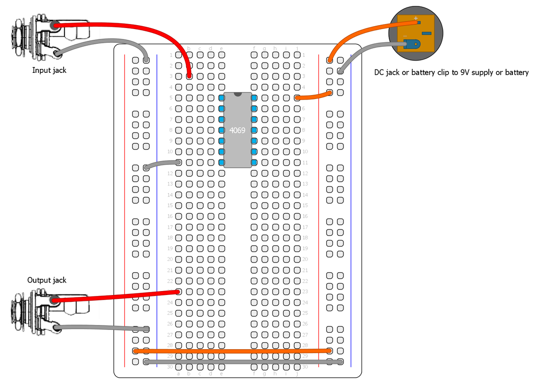
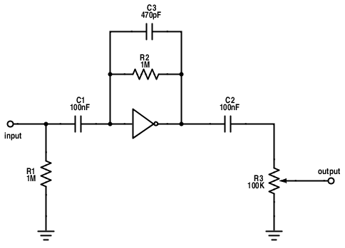
4. Pulldown/up resistors
These resistors are often needed in CMOS circuits. They are useful when we want to force a high or low output state when the input is not changing, but still leave the input able to accept a input signal. They are typically a high value from 10K - 100K and goes to ground (pulldown) or V+ (pullup) at the input of the gate. For example, if we have a gated oscillator on the input and we want  to make sure the output always goes to ground when the oscillator is off we need a pullup resistor at the input (assuming the gate is inverting). We will use a few pratical examples later on.

5. Lets breadboard the "CMOS'ifier", a simple square wave fuzz.

We will use this circuit as the front end for the guitar signal, so we can do other things later on, such as octave down. But it also makes a pretty cool fuzz on it's own.
For this we will use a CD4069 chip, simply because it has a easier pinout than the CD4049 and takes less space on the breadboard. First, lets take a look at the pinout of this chip. Lets connect input/output jacks, power and ground to the breadboard and the chip like this (these connections will not be shown later):
Picture
CD4069 pinout
Picture
Stage 1. Preamp
Our first stage of our circuit will be boosting the guitar signal into logic levels. This is a gainstage similar to many CMOS based distortions, such as the classic Tube Sound Fuzz by Craig Anderton. This is one of the exceptions to the digital logic and can only be done with the CD4069/CD4049. It gives a very pleasing distortion, but has the drawback of being rather noisy.
We will configure one stage of the inverter by adding negative feedback, using a resistor from the input to the output of the inverter and decoupling capacitors.

  • R1: Load resistor
  • R2: Sets the gain of the amplifier. Try a 1M trimmer/pot here insted for controlling the gain.
  • C1 and C2: Decoupling capacitors. This is always needed at the input and output of a circuit, but it's also nessecery for the input of a linear amplifier to work properly.
  • R3: voltage divider trimmer to control the output volume.
  • C3: optional lowpass filter cap. Can be anything from 100pf to 47nF. How much treble it cuts depends on the value of R2 aswell. Experiment with different values!
Picture
Stage 1: linear amplifier gainstage
A CMOS inverter configured as a linear amplifier doesn't need an external voltage reference for bias, so very few parts are needed to make it work. It will self bias throught the feedback resistor thanks to the operation of the internal MOSFET output pair. This works best with the unbuffered (UBE) versions of the chips.
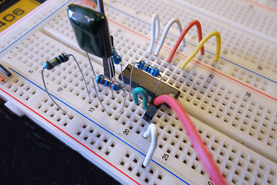
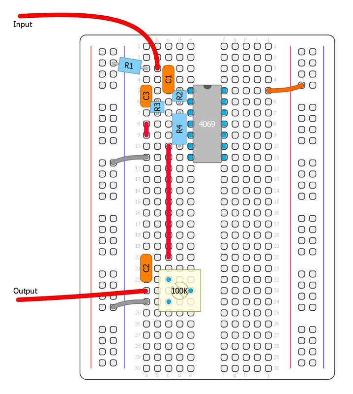
Lets put it up on the breadboard. Notice the green wires in the first image that are used to disable all the unused inputs. This will not be shown later, but it's a good pratice to always disable any unused input. The second image shows the same circuit with a trimmer for gain control. Put several gainstages in series for a sweet sounding distortion. I usually have two gainstages in my designs when I have one extra inverter left over.
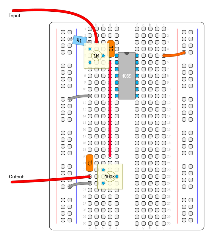
We can use any circuit to boost the signal into logic levels, transistor-based or op amp, but the advantage with this method is that we're only used 1/6 of one chip. So the rest of the inverters can still be used for other things, oscillators, LFO, filters ect. and this will save us some space. Another easy way is to use a LM386 amplifier chip and boost the signals into a squarewave (common in many Tim Escobedo designs), or a op amp comparator.


Stage 2. Schmitt Trigger
This stage completes the "CMOS'ifier". It will turn the signal into a pure square wave, making it compatible with other CMOS chips and eliminating noise from the guitar pickup when not playing. This part is inserted before the output capacitor.

R3 and R4 sets the upper and lower thresholds for the schmitt trigger. It's best to leave R4 at 1M and experiment with the lower threshold resistor R3. Higher values will make it more gated, but low values can result in oscillation. Here we need to find the sweetspot that depends on how strong input signal we are getting. Increasing the value of C3 (1nF - 22nF) can also help against oscillation, noise and misstriggering. Very low output pickups may sound too gated, in that case use two preamp stages in series before the schmitt trigger to increase the sustain.

If we have a schmitt trigger chip (CD40106 or CD4093) in our design we can just use one gate of that chip insted directly after our preamp stage. It's not as versatile, as it has a fixed hysteresis. In that case a pulldown resistor (100K to ground should always be used at the first schmitt trigger input).

​
How does the Schmitt Trigger work exactly?
R3/R4 forms a voltage divider that offset the signal (it also attenuates it). When the schmitt trigger output goes low, R4 is effectively connected to ground (via the second inverter output). This offsets the input signal which gets pulled closer to ground, so when the signal starts to swing in the opposite direction it has to rise a bit further to cross the half supply voltage threshold (the chip threshold always stays the same) and vice versa: when the schmitt trigger output goes high, R4 is connected to your positive supply voltage via the output, so then the signal is pulled closer to V+ and needs to swing a bit lower to cross the threshold. Thus creating hysteresis. For this to work, the output needs to be non-inverting, hence the two inverter gates in series. This also helps the process as the first inverter is isolated from the feedback resistor.

​In the next part, we'll have a look at doing something a bit more advanced - several few ways to achieve octave down!

I hope this series is interesting. I'm trying to keep it as basic as possible, but it will become more advanced in later parts. Please let me know what you think and if there is anything I can improve. Thanks!

UPDATED 2023-10-31: Fixed the schematic numbering not matching the breadboard and added a bit more info about the operation of the Schmitt Trigger/bias.

Picture
The complete "CMOS'ifier" fuzz
Picture
The complete circuit on the breadboard
What is signal offset?
Any alternating current (like a guitar signal) always have a DC bias point. It centers the signal to swing above and below a specific voltage, sometimes referred to as the DC component of the signal.

In a dual supply circuit, the signal usually swings positive and negative centered around ground (0 volts) and in a typical single supply circuit like a guitar pedal we have a Voltage Reference  (Vref) that the signal swings around. Ideally at 4.5 volts in a circuit driven by a 9V battery, to get maximum usable range.

This bias can be offset/shifted up or down which is part of how the schmitt trigger operates. It's very common to shift control voltages in synthesizers.

Next part: CMOS workshop part 3
29 Comments

CMOS workshop part 1 - basics

8/19/2015

5 Comments

 
Many of my designs are based around CMOS chips and a few people has asked me if I know any good resource for stompbox designs based on CMOS. So I thought it might be fun to share alittle of my knowledge of the CMOS basics and hopefully you will learn something and will be able to experiment with your own CMOS based circuits. :)

We will use the breadboard later, but first, lets start with the basics (the boring stuff...)

CMOS chips are based on MOSFET transistors, unlike the earlier TTL logic chips that are based on BJT transistors. I won't go into detail on how they work on the insides. For that I really recommend reading the book: The CMOS Cookbook. It's been a huge help and inspiration for me.

1. CMOS LOGIC
The first thing one must understand is that CMOS works with digital logic:
The output will be either high or low, depending on the voltage at the input(s).

These input/output states are often also called "true or false", "on or off", "1 or 0". The CMOS chips are basically acting like digital switches that can either source or sink current.
​
High = positive supply rail (v+)
Low = ground

There are some CMOS chips that doesn't follow this digital logic, for more specialized functions (like a Phase Locked Loop). Some chips can also have a third disconnected output state (floating/undefined state).

This means that no matter which kind of waveshape we put into a typical CMOS logic chip, the output will always be a square wave. There is no in-between, no dynamic range, just 1's and 0's. The output logic changes at about halfway up the power-supply voltage, so to be able to use a CMOS chip with a guitar signal, the signal needs to be boosted into logic levels, then preferably made into a square wave: digitalizing the signal (in a crude way).

​This is the reason you don't see a gain control on many of my designs and why it often sounds totally fuzzy. A square wave is as distorted as it can get, as the nature of the square wave introduces alot of odd harmonics into the signal. This is also the reason why the output of a CMOS based guitar effect have a gated sound with a decay that dies abruptly (as the input signal falls below the schmitt trigger threshold).

More about schmitt triggers later.
Picture
The Arcadiator uses 3 CMOS chips
Picture
Don Lancaster's CMOS Cookbook
Keep in mind that there's a limit on how much current the outputs can source and sink which can vary alot between different CMOS chips, so check the datasheet for the chip you are using.

Especially if you are driving LED's directly, then you need to use a current limiting resistor that is big enough to not draw more current than the gate can handle.

Here's a short video of my oscilloscope that displays a guitar signal that is boosted to reach logic levels, then later fed through a CMOS schmitt trigger to make it a square wave so it will play along with other CMOS chips. No audio output is connected in this video, it's for the visuals only, so you can get a idea of how the waveshapes look when it's getting "CMOS'ified". :)

Later we will breadboard the circuit I used, a very basic square wave fuzz, so you can listen yourself to how it sounds.

But first, lets iron out alittle more of the basics...

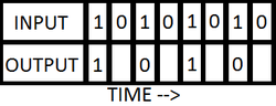
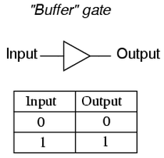
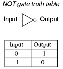
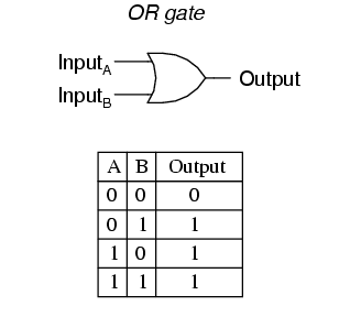
2. GATES
A single CMOS input/output is called a "Logic Gate". Sometimes each gate can have several inputs. A chip usually consists of several identical gates that can be used independently. In the datasheets we will find something called a "Truth Table". It tells us how the gates operates based on their logic type. Lets take a look at a few different chips and their logic.

Buffer (CD4050)
This chip is rarely used in stompbox applications. But I wanted to use it as an example. As you can see by the Truth Table, if the input is high the output is high, and if the input is low the output is low. So this chip is simply a buffer (mostly used for interfacing to TLL logic).
Picture
Buffer schematic symbol and truth table
Inverter (CD4069/CD4049)
This chips, also sometimes called a NOT gate (or hex inverter because the chip has 6 gates), inverts the input. If the input if low, the output is high and vice versa. The output is 180 degress out of phase with the input. Notice the small circle (knot) at the output on the schematic symbol. This means that the gate is inverting.

This is probably one of my favourite CMOS chips since they also can be configured as linear amplifiers aswell. More about that later.
Picture
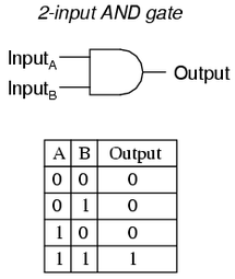
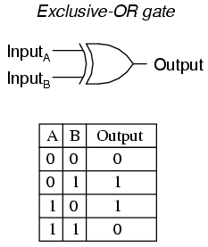
Now the logic gets alittle trickier...

AND GATE (CD4081)
This chip has four AND gates. Each gate has two inputs. With either or both inputs low, the output will be low; with both inputs high, the output will be high.

Both input A and input B needs to be high for the output to be high, hence the name "AND gate".
Picture
NAND gate (CD4011)
This is basically the same as a AND gate, except that it inverts the output. It can be useful when doing gated oscillators. I used a NAND schmitt trigger chip (the CD4093) for that application in my Flawed Logic Fuzz. We will breadboard a gated oscillator later on.

NAND stands for "NOT AND". Remember that a NOT gate is an inverter.
Picture

OR GATE (CD4071)
This chip has four OR gates. Each gate has two inputs. With either or both inputs high, the output will be high; With both inputs low, the output will be low.

Input A or Input B needs to be high for the output to be high, hence the name "OR gate".

NOR GATE (CD4001)
You can probably guess by now that the NOR gate (NOT OR) is an inverting OR gate, so I will not add the NOR gate schematic symbol and truth table.
Picture
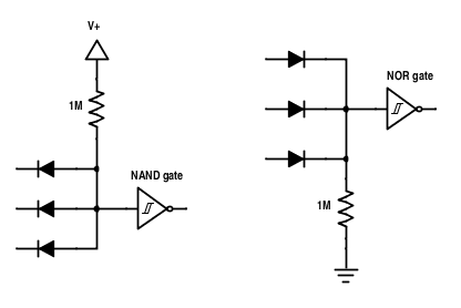
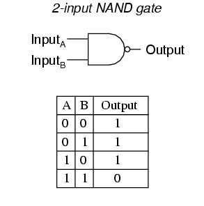
NAND and NOR gate are sometimes called the universal gates, since they both can be used to form all the other basic logic gates.
Is it starting to make sense? Let have a look at a couple of more...

XOR GATE (CD4070)
This chip has four Exclusive OR gates. It also has two inputs per gate. It's a very versatile chip, because one of the inputs decides if the gate is inverting or non-inverting by tieing the input to either +V (non-inverting) or ground (inverting). In the Arcadiator I use this feature to make the alternating octaves - more on this later. This chip can also be used as a comparator as identical inputs gives a low output and different inputs gives a high output. So basically, if two different signals is put into the two inputs the output is the sum of the differences of those two (hence the name "exclusive or gate"). This is patrially how my ring mod The Corruptor works.
Picture

SCHMITT TRIGGER (CD40106)
Here's another very versatile chip. It's an inverter, but it has something called hysteresis built into the chip which makes it a schmitt trigger. Hysteresis is basically a "noise immunity zone". For example, if we use a 5 volt supply, the input signal will have to reach above 2.9 volts for the output to go low and it will have to drop down to belop 2.3 volts for the output to go high. That's a 0,6 volt hysteresis that will keep out any noise at the input that is below the threshold. The built in hysteresis also lets us configure this chip with diodes and resistors to do other logic funtions: multiple inputs NAND or NOR gates, pulse width modulation and much more.
Picture
Schmitt trigger schematic symbol

Those are a few basic CMOS logic chips. We'll use them later to breadboard stuff or analyze a few of my designs.

I mentioned before that not all CMOS chips follows this logic. We have many exceptions, switches, linear amplifiers, MOSFET cmos chips ect. I will cover a few of those later.

Lets stop there for a while. This post turned out alot bigger than I imagined and it can be a bit overwhelming! I had a hard time wrapping my head around this when I started out. If you are confused by the logic inputs and outputs, don't worry. In the next part we'll actually make something useful, a simple squarewave fuzz. The breadboard is a great learning platform, and by making a few small circuits I hope you will begin to understand these logic alittle better.

Please let me know what you think of this post and if you find anything that is incorrect.
/ Fredrik

UPDATED with some additional info and minor clarifications 2023-10-31.

Next part: CMOS workshop part 2
5 Comments

Flying Guillotine Fuzz

8/19/2015

4 Comments

 
EDIT 2014-08-19
I added a single layer PCB layout to the bottom of the post that fits better in a 1590B. Effects layouts also made an excellent perf and PCB layout, check it out at: http://effectslayouts.blogspot.se/2015/07/flying-guillotine-fuzz.html

Here's a fuzz circuit I made up about a year ago that turned out pretty cool. The front end, tonestack and the output stage are all borrowed from the Big Muff, but the two Muff gainstages is replaced with a discrete op amp (by Joe Davission) modified with a odd feedback transistor clipping configuration.
In the soundclip the gain is maxed, tone at noon and volume at about 9 o clock.
I got the name from one of my favourite movies. :)
flying_guillotine_pdf.pdf
File Size: 159 kb
File Type: pdf
Download File

flying_guillotine_vero.gif
File Size: 43 kb
File Type: gif
Download File

4 Comments

Arcadiator release

7/24/2015

2 Comments

 
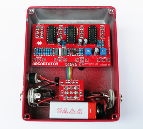
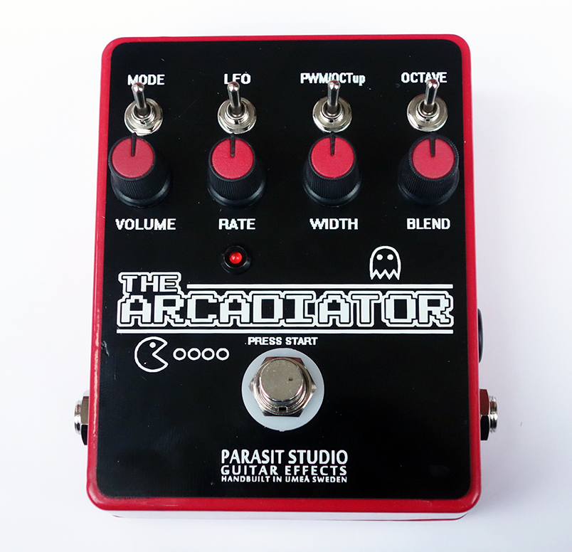
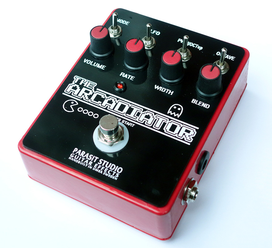
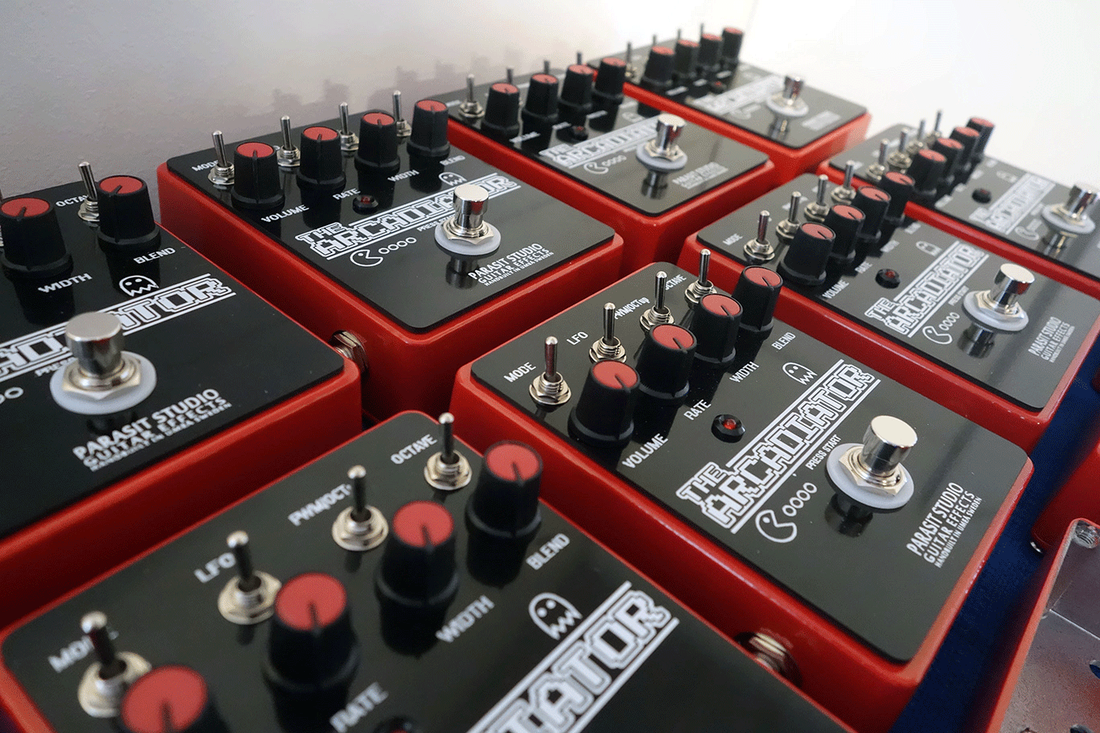
Update 2015-07-24
The Arcadiator is now released and avaliable in the shop!

The first batch is limited to 30 pedals, 27 sold in the shop (25 red and two white).

These are sold at a special introductory price. At first I was going to sell the first 10 pedals only at this price. But I have had some problems with the production of the faceplate, so I decided to sell them all for this price. The faceplate have minor beauty flaws, but don't be alarmed, it's just barely noticable when you look at it from a certain angle. All in all i'm very satisfied with how these pedals turned out.

I'm going on a vacation trip soon (31/7) and will be away for a about one week. So order now and I will have it shipped out before leaving for vacation. I will start on the second batch when I get home from my vacation. I need to check up on alternative means of producing the faceplate, so the next batch may take up to 3 months before they are avaliable.
2 Comments
<<Previous
Forward>>
  • DIY GUITAR EFFECTS
    • Original Effects
    • Building blog
    • DIY Gallery
    • Stripboard layouts
    • Articles
  • SHOP
  • BUILD DOCS
  • DISTRIBUTORS
  • ABOUT