8 Comments
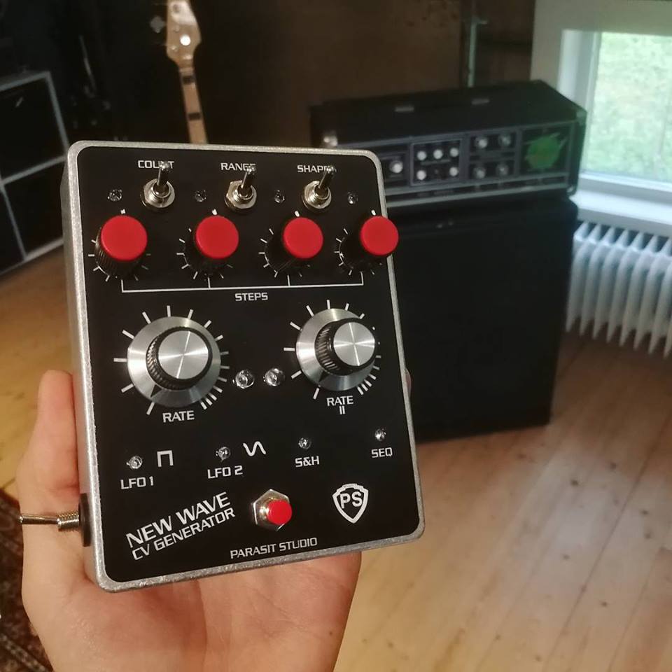
I'm happy to announce two new projects coming soon, summer sale and more! It's been a long time since I posted anything. I've been very busy lately, working, touring and doing other projects. It's been hard just to keep up with the emails i'm getting every day, let alone work on new stuff. But in the last couple of week I've finally had some spare time, and I've managed to complete a couple of projects that has been brewing for a long time. I hope you find these interesting. :) Coming soon!
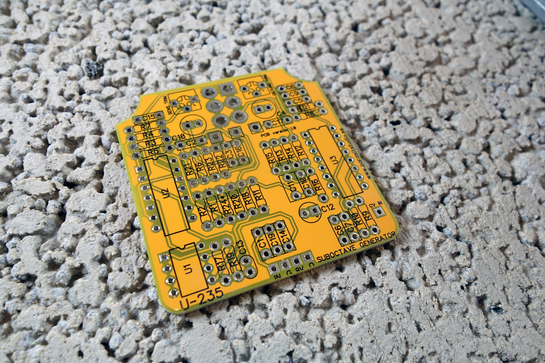
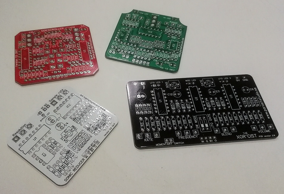
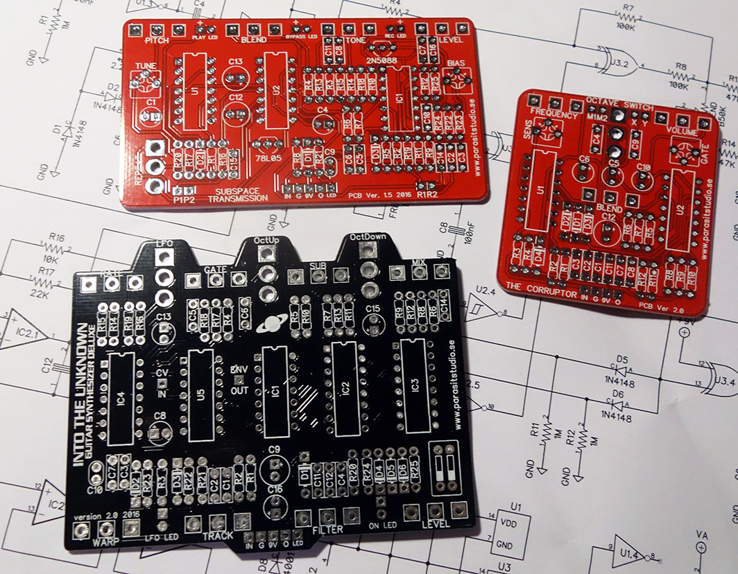
More into coming soon on the new projects! I expect about 5-8 weeks until release. New PCB versions released!
SUMMER SALE!To celebrate these news I now offer a 10% discount in the webshop.
Just enter the code "summersale" at the checkout. Valid until 5/7. That wraps up this long overdue post. I hope everyone out there is having a great summer. Cheers // Fredrik
It's time for another part of the CMOS Workshop series. :) This part will be about octave up circuits (aka frequency doublers). 
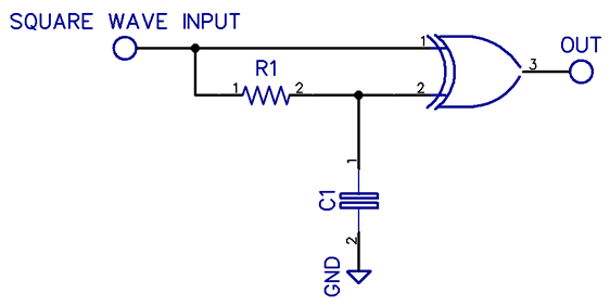
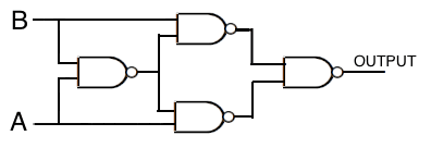
1. XOR gate (CD4070)The CD4070 is ideal for this purpose and require very little extra components.
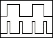
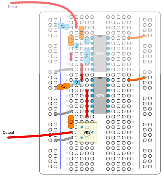
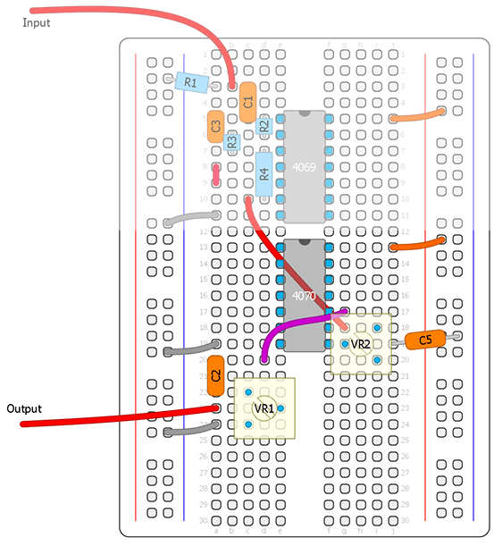
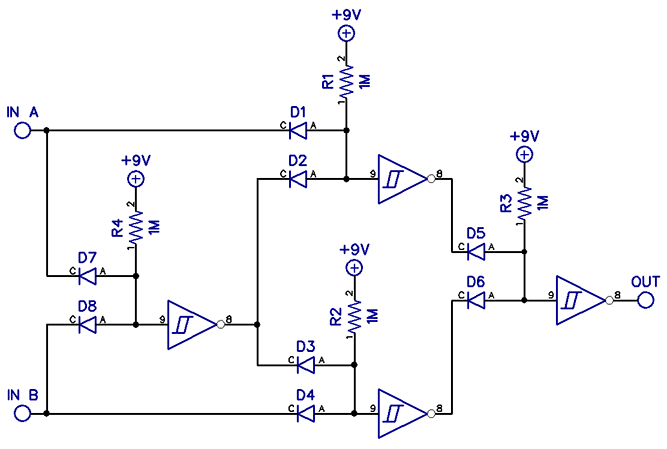
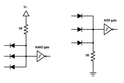
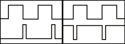
XOR logic: For the output to go high, both inputs needs to be at a different state By connecting our square wave to both inputs and delaying one of the inputs slightly, there will be a brief moment when the inputs are in different states. At this moment the output will go high, thus creating a short pulse wave at the output every time the input goes high or low. The delay is made out of a simple RC filter. It will round out the square wave, so that it takes alittle longer for each transition to cross the switching threshold of the logic gate. Lets try this circuit on the breadboard. Remember to always disable all the unused inputs.
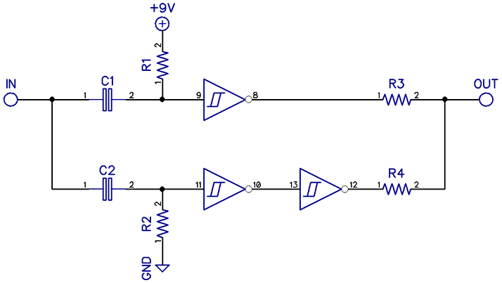
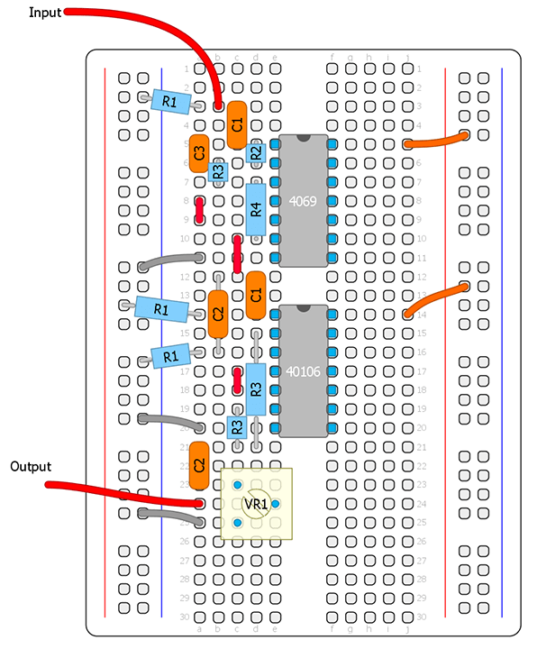
Here we can play around with different values for the RC filter. It will change the width of the pulses and the character of the sound. For C5 (C1 on the schematic) try a 4.7nF - 47nF value. For R5 (R1 on the schematic) try 10K-500K. In the 1B example I've replaced R5 with a trimmer and for convenience I chose another gate. The top greyed out part is the gainstage and schmitt trigger front end from the CMOS Workshop part 2 so you will have to check the other component values there. Notice that the pulse width can get too narrow or wide for the octave up effect to work. As a rule of thumb you don't want the pulses to be too narrow because it will sound bad, and you don't want the pulses too wide because then it won't track properly on the entire fretboard.
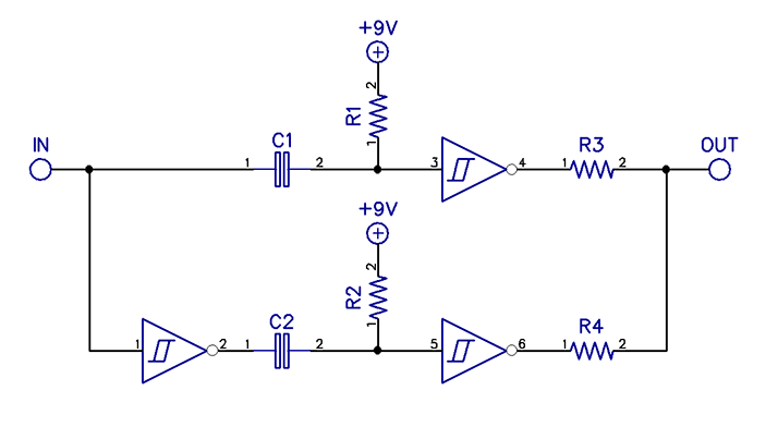
The B schematic is just another way of doing the same thing. I just moved the inverter to the input insted.
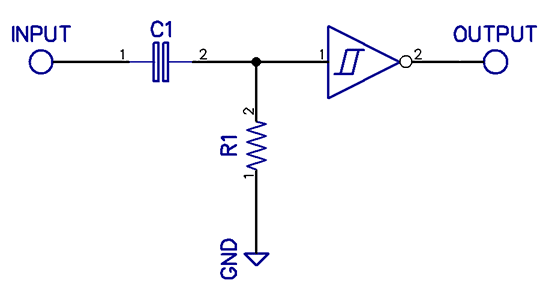
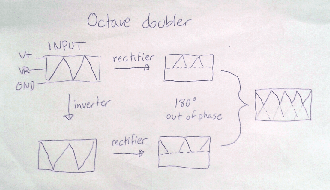
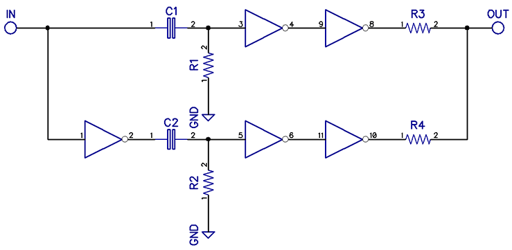
4. NOT gate (CD4069)There's one last version I would like to include in the article, similar to the schmitt trigger one, except that it uses regular inverters.
That's all I had for this part.
I've given some examples of how to make frequency doublers with edge detector circuits using at least 5 different CMOS chips (if you count the schmitt trigger variations). Which one you choose will probably depend on the rest of the circuit you are making. Maybe you already need a schmitt trigger chip in your circuit to do other functions, then example nr 2 is better because you will still have 3 gates left over (if using a CD40106) insted of adding an xor chip to only do one thing. Personally I prefer to keep the chip count as low as possible even if it adds more components. It usually takes less time to solder a few extra resistors and caps then having to solder another 14 or 16 pin chip (which also takes more space on the PCB). It's all about convenience. As I've shown, there's usually several ways to do the same thing when working with CMOS. Remember that we're dealing with 1's and 0's, so no matter which chip/method you use it will basically sound the same (if the pulse width is equal). Same goes for the octave down methods in the previous part. However, there is a clearly sounding difference between edge trigger or rectifier doublers, or PLL VCO frequency doublers (as used in the Into the Unknown guitar synth) which I will cover in a later part. But next part will be about oscillators and LFO's. We will breadboard some fun stuff, as I've promised :) UPDATED 2023-10-31: Some minor spelling corrections.
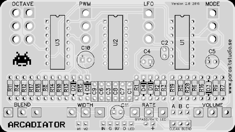
PCB's avaliable now in the shop
|
|||||||||||||||||||||||||||||||||||||||||||||||||||||||||||


