PARASIT STUDIO
  • DIY GUITAR EFFECTS
    • Original Effects
    • Building blog
    • DIY Gallery
    • Stripboard layouts
    • Articles
  • SHOP
  • BUILD DOCS
  • ABOUT

New DIY project - The C19 Databus Drive released!

9/18/2020

4 Comments

 
A new DIY is released - The Databus Drive. :)
It's a massive guitar synthesizer with a 16x16 LED matrix. The goal of this design was to keep it microcontroller free, so it's entirely CMOS based (with the exception of two LED driver chips). It has two signal paths with both octave up, octave down, sawtooth and square waveshapes, and two types of modulation, vibrato and phaser. C19 stands for "CMOS 19" (the number of chips on the board).

The LED matrix was originally developed as an addon for the Multiwave Mega, but I scrapped that idea when the Mega became partially Attiny based, thus uncompatible. The modulation features is also something that I have been wanting to add to an all CMOS based project, but I have always felt that the number of chips required is too high. It's easily done with a single microcontroller, but what's the fun it that?.. :P

All these ideas has come together in the C19 Databus Drive, and what made this feel like a feasible project despite the big number of chips were the idea of a transparent cover, to display all the circuitboard and the LED matrix. I got this idea from the Gigatron TTL computer that I built for myself a while ago (it's a really cool project). But I also love the look of old 8-bit computer motherboards with through hole components, such as the C64.
I had alot of fun putting together this little multitrack demo for the Databus Drive. The drums are from a C64 (with the Mssiah sequencer cartridge) and there's a small addon from a Yamaha PSR-36, but all the other sounds comes from the Databus Drive.

What games and movies that you can spot in the demo? :)
Picture
This project is avaliable now!
  • PCB avaliable in the webshop.
  • Complete DIY kit avaliable from Musikding

Check out this page for more info, documents ect.
Picture
4 Comments

Work in progress june 2020

5/6/2020

9 Comments

 
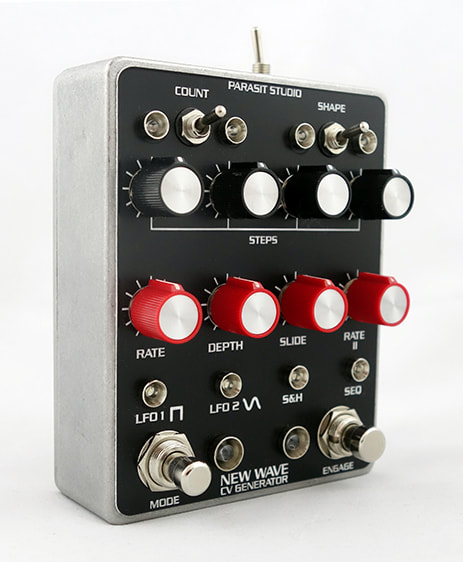
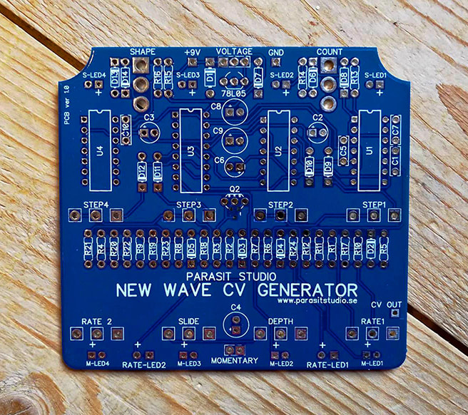
Here's what I have been up to lately. Check out the video below for some talk and sound samples. :)
This is the first time i've done a video to talk about stuff that i'm working on. I'm very uncomfortable to speak in english and to hear my own voice haha, but i'm working on it.

​Perhaps if I get a bit more confident I'll do some video based tutorials (CMOS, Attiny prgramming ect.) in the future. Let me know if that's something that you would like to see.

Here's a summary with some additional info.

The Monobius 8-bit Micro System
This was a Attiny84 based project with a card/cartridge-slot that I was working on earlier this year in the winter. It was supposed to have 3-4 cards with programs based on old Parasit Studio designs, such as the Arcadiator, Xor'cist ect. but with a few more bonus features.

However, I decided to scrap the card idea, since it felt like it was too much trouble for a gimmick, so now I'm working on a stand alone version instead that I think will be really good. This one will only be avaliable as a fully assembled pedal, not DIY (Sorry).
Picture

The Databus Drive
The second project that i'm working on right now is called the Databus Drive, and it's a huge guitar synth inspired by old 8-bit computers, especially the Gigatron TTL DIY computer that I have built for myself a while ago. 

The idea is that the Databus Drive will also be built inside a custom wooden enclosure with a clear transparent top cover. It's 100% CMOS based (I enjoy developing these kinds of projects alot more than microcontroller based projects) and features a 16x16 LED matrix oscilloscope that I originally developed as an addon for the Multiwave MEGA (before it became Attiny based).
​
Picture
PCB render - final version will be white with black silkscreen
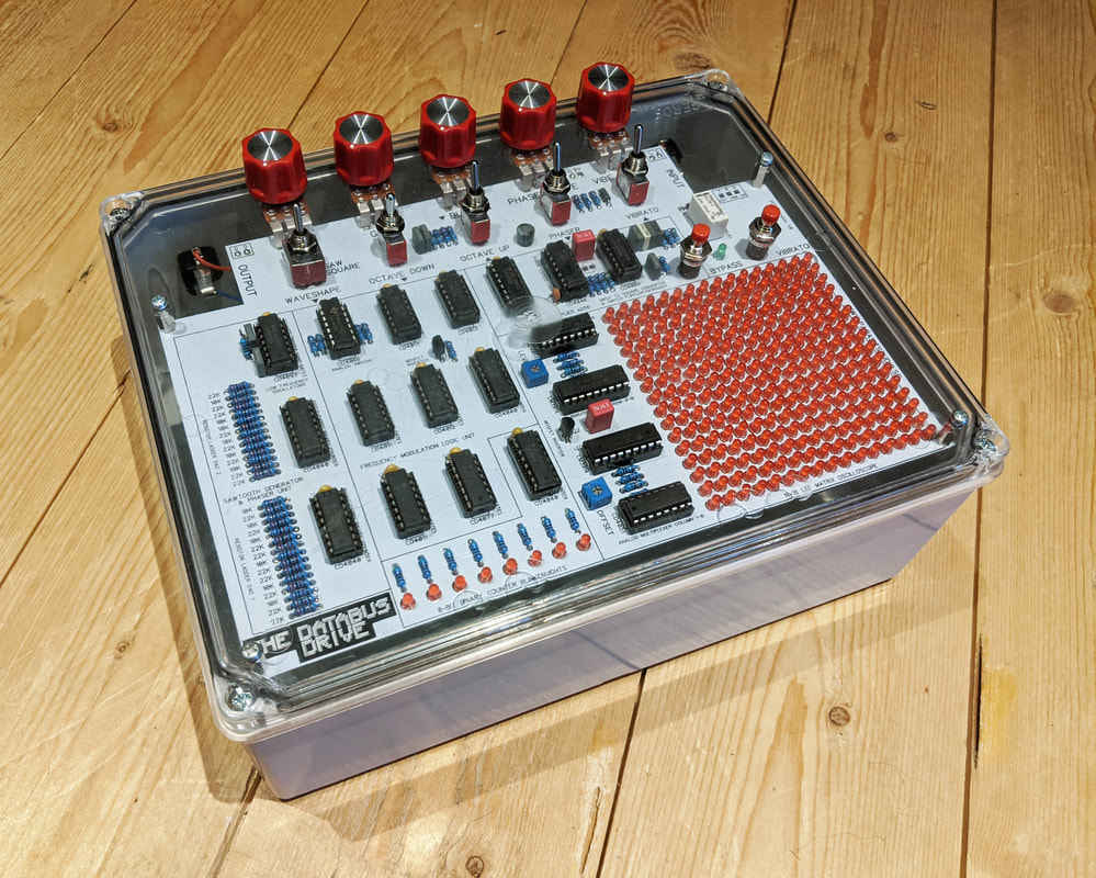
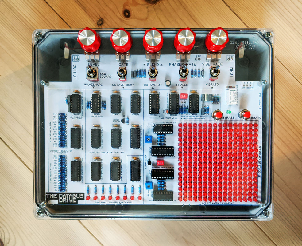
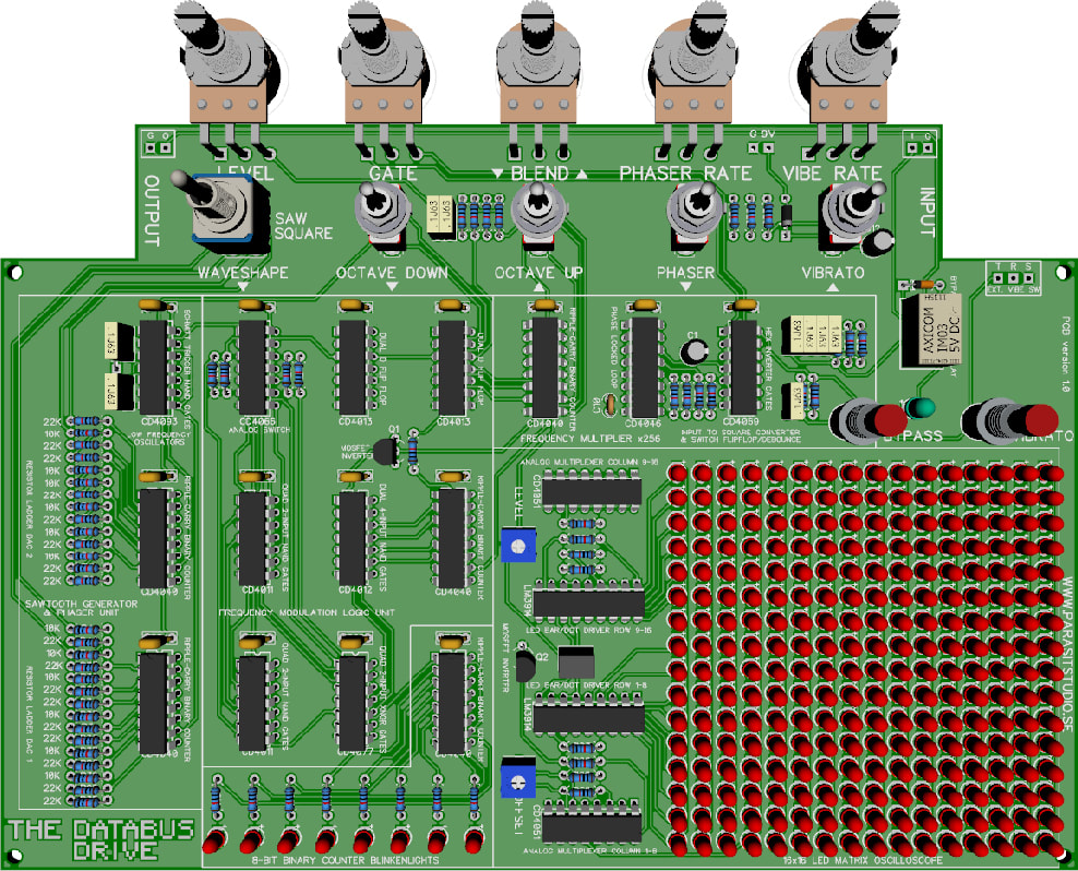
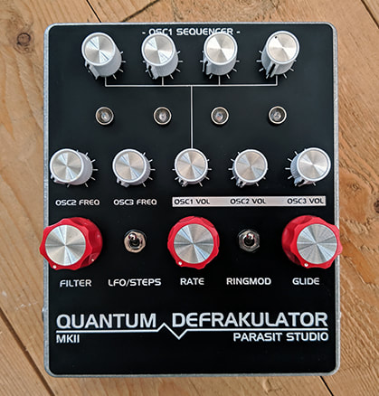
It has a phaser and a vibrato that are both kinda complicated features to pull off with CMOS only, hence the big number of chips in this one. I had these features going with a microcontroller, but I thought that it was fun to see if it could be done with CMOS instead. Otherwise it's nothing super special. No filter or envelopes. But I think it will be a very cool effect as a whole. Right now i'm waiting for the prototype PCB's and a ton of LEDs to arrive. Can't wait to build this one. :)

If enough people are interested in this one, then I will do a limited run of PCB's for DIY (it's a huge and expensive board). Just note that the PCB isn't designed for any standard enclosure size (but there are some plastic electronic boxes with transparent covers that can suit the PCB).

A few custom builds
I usually don't accept custom requests, but because of the Corona Situation i've been building a few pedals for birthday gifts ect.
A custom Green Currant Tremolo, built for a member of the band Vidro.
​Check them out if you like raw hardcore punk. :)
Picture
The "Darby Fuzz" - A germanium Fuzzface variant with russian NOS germanium transistors and a discrete voltage inverter.

I built the board a long time ago and decided to finally box it up. It was built/designed specifically for this article: https://www.parasitstudio.se/building-blog/manhattan-style-pedalbuilding

If you are interested in the transistor based voltage inverter, you might want to draw up a schematic from the manhattan style layout (I don't have the schematic any longer), and check out Dave Jones video on the theory behind the Cockcroft-Walton Multiplier (same principle can be used to generate negative voltages aswell).
https://youtu.be/ep3D_LC2UzU
Picture
A custom modded EA tremolo

​Not much to say about this one. I built it on singlesided copperboard "manhattan style" aswell. It's just such an enjoyable way of building simpler circuits like this one, and the big ground plane makes it good for low noise (one of the reasons the manhattan style is popular with ham radio DIY electronics).
Picture

PCBWay PCB Assembly Service
When I was designing the Monobius pedal I was contacted by PCBWay that wanted me to try their PCB service for free (they even paid for the shipping) if I shared my opinion on their service. I wasn't interested at first, but I decided to try their PCB assembly service since I've never used an assembly service before and it could be a great time saver.

So this post is sponsored by PCBWay since I own them a mention. They guided me through the whole process of ordering and they were very easy to communicate with and the board turned out great, so i'm happy to recommend them and use their service in the future. :)​
Picture
Picture
One of the Monobius cards being designed (in Diptrace)
PCBWay made the 10x Monobius cards for me with preassembled chips. Now, as it turns out, these cards will not be used, but it nice to learn how the PCB assembly ordering process in case I want to use it for a bigger project in the future.

That's all for now. For more frequent updates, please check out Parasit Studio on Instagram and Facebook.

Stay safe and keep up the DIY spirit. :)
/ Fredrik
9 Comments

Covid 19

3/29/2020

9 Comments

 
The corona virus is effecting all our lives.

As a person with chronic autoimmune disease i'm worried for my own health. I'm also concerned for my old and frail parents. Luckely, the situation here in Sweden is still mild compared to many other countries, but I guess that we haven't seen the worst yet. Sweden has a more liberal approach with less restrictions than its neighbouring countries.  Whether it's good or bad is up for debate.

Beside the loss of lives, it's very upsetting to see alot of people are loosing their jobs and businesses to face an uncertain future. I make my living as a freelance sound engineer and I normally have 2-3 months ahead fully booked with shows and lectures ect. So far every single job for the foreseeable future has been cancelled (Sweden currently has a 50 people cap restriction). My only income now is from the Parasit Studio webshop and cooperation with Musikding for the DIY kits. It's not nearly enough to make a living, but my wife can still work so we will manage. I'm not that concered with my income as I am about my health.

The only positive thing about all this is that alot of people now have much more time for building pedals. Myself included, so alot of fully assembled Parasit Studio pedals are coming, and perhaps a new DIY project or two aswell. :)

That said, if you are planning to build a Parasit Studio project using one of my vero layouts, please consider buying a PCB insted. I would really appreciate the support. You can also donate (link at the bottom of the About page). Thanks!

The webshop will still be up and running as usual. So far the postal service is shipping normally, at least to US and all EU countries.

Stay safe
/ Fredrik
9 Comments

The Quantum Defrakulator MK2 released

8/23/2019

3 Comments

 
While working on the Multiwave Mega developement, I got stuck and almost gave up on the whole project, so I decided aim my attention elsewhere for a while to regain my sanity...  I figured that the Quantum Defrakulator drone synth could use a few more features. After all, the first version was as barebones as possible.

So here's the new MK2 version. :)
PCB avaliable now in the webshop and complete kit avaliable from www.musikding.de
Picture
3 Comments

Coming soon: The Multiwave Mega

8/23/2019

9 Comments

 
For many months now, I've spent hundreds of hours working on a new DIY project - The Multiwave Mega. I'm very happy to say that the developement is finally done, and I'm just waiting for the prototype PCB to arrive so it's hopefully not too far until release.

The Mega is a guitar synth that is quite different than anything I have done before.
​It's a analog/digital hybrid. On the analog side we have a preamp, sample and hold (for infinite sustain aka "drone mode") and a resonant lowpass filter, and on the digital side we have a microcontroller that handles two oscillators, filter envelopes and an LFO.

Key features:
* Two oscillators with several waveshapes that can be blended together and detuned
* Resonant filter with envelope control that can be triggered by the guitar input
* Sustain mode, which will hold a note forever. It can also be triggered by the guitar
* LFO with different waveshapes for modulating the amplitude and/or frequency

The oscillators are wavetable based, which means that every waveshape is stored as a series of numbers that represents voltage over time (PWM duty cycle) for a single waveshape cycle. It has a 6-bit resolution (64 steps) for the oscillators and the LFO,
and a 7-bits resolution (128 steps) for the filter envelopes.
​
More info coming soon!
Here's a short video where i'm playing around with the Mega on the breadboard, in drone mode with the LFO going to create some interesting sounds.
Picture
Faceplate graphics
Picture
A rendition of the PCB
9 Comments

New release and hidden feature revealed!

1/14/2019

7 Comments


The Multiwave Guitar Synthesizer

Today i'm releasing this new DIY project.

I've been playing around with the idea of creating other waveshapes then square waves for different sound possibilites. Saw and triangle is alot more challenging to produce out of a guitar signal, at least when doing it in an analog fashion.

The Multiwave is the result of alot of developing time. This is actually my third working design. The first one wasn't tracking that good and the second design needed an expensive chip (but actually had a perfect waveshape). So I finally settled with this version, which doesn't perform the best, but only uses common parts so anyone can build it without spending too much.

I hope you like it. :)

More info about the Multiwave Guitar Synth

The 1985 Guitar Synth hidden feature revealed...

The 1985 Guitar Synth was released in december, and I didn't reveal what the hidden feature was, but since so many people has asking for it - here's a video about it.

You could probably guess what it is just by looking at the video thumbnail. :)

Coding the hidden feature actually took alot of time. The actual guitar effect code took less then 10% of the program memory, but the tune itself took needed all the remaining space. I even had to cut down the track to make it fit.

I hope that you enjoy the novelty feature. :)

More info about 1985 Guitar Synth

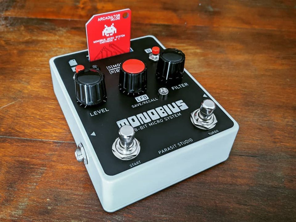
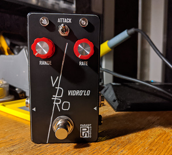
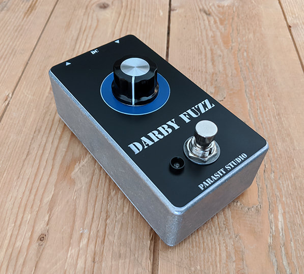
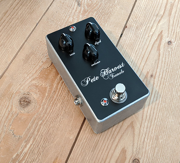
I plan on releasing a few more "normal" pedals going forward, so stay tuned.
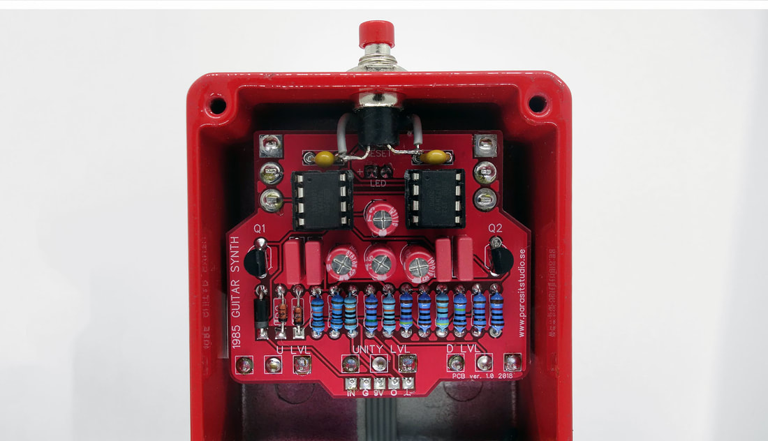
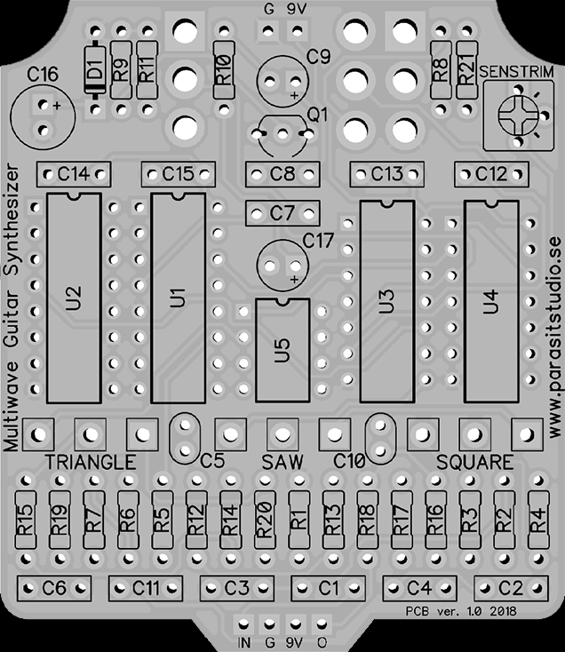
/ Fredrik
7 Comments

December 2018 update

12/10/2018

1 Comment

 
Hi folks!
Here' alittle bit of news. :)

New DIY project release!

Today it's the release of a new DIY project - the 1985 Guitar Synth
The 1985 Guitar Synth is the first fully digital Parasit DIY project followed by the (non-diy) Bitbreaker Deluxe.

The goal with the Bitbreaker Deluxe was to make an octave down pedal with as few components as possible (I wanted it to fit a 1590A enclosure), similar to the 8-bitar, but with more features. This was only possible using a microcontroller chip - The Attiny85. It is a really cool chip, because it doesn't need any external components to run and it's very small. It's a bit harder to program for, but I enjoyed the challenge/limitations.

The 1985 Guitar Synth takes the Bitbreaker Deluxe octave down functionality (but a bit simplified with 3 modes insted of 5) and adds a second oscillator. This new oscillator is based on a frequency counter, which makes it extra glitchy unlike anything I've done before. I also added a hidden feature, which took up most of the program memory...
​
​I hope you like it. :)
Picture
The 1985 "robot face" PCB
I got into programming this summer, because it's something i've been wanting to learn for a long time. It has opened up a world of possibilites, so a few upcoming (non-diy) pedals will have digital chips. But I'll try to keep most of the future DIY projects being fully analog/CMOS based, since there's a bit of hassle to sell pre-programmed chips.

Upcoming DIY Projects

  • The Multiwave Guitar Synth
I have been wanting to do a guitar synth with other waveshapes beside square waves. This has resulted in the Multiwave Guitar Synth which will have sawtooth, triangle, square and a special ringmod mode aswell. It's a fully analog pedal. I expect this to be released very soon (early january if everything goes well).

  • ASR pedal (I have no name for this one yet)
An ADSR (which stands for Attack, Decay, Sustain, Release) is something you usually find in synthesizers to control the envelope of filters and amplifiers. I've been working on something similar for guitar, with the Attack, Sustain and Release features. It will be triggered with either a foodswitch or an envelope follower to control a VCA. So that you can use it as a swell/fade in pedal, a wierd tremolo (it will have an auto-retrigger feature) or a glorified killswitch. It will have a external trigg input and CV output for use with other gear. This pedal is still in developement.

That's all for now. More info about these projects coming soon!

/ Fredrik
Picture
The Multiwave Guitar Synth PCB
1 Comment

Manhattan style pedalbuilding

11/2/2017

6 Comments

 
The "Manhattan style" is a very old method of circuit construction. It's especially popular among radio amateurs for high frequency circuits because it has a solid ground plane that helps to reduce interference and noise.

​It's also a fun way to build simple discrete circuits. :)

​Pros:
  • Fast build time (at least compared to etching boards)
  • Easy building and schematic to layout conversion
  • Great for quiet noise free-builds (superior to stripboard, perfboard and tagboard in this respect)
Cons:
  • Doesn't suit IC chips
  • Only good for smaller less complex circuits
Picture
The Darby Fuzz
Some people would probably not agree with the disadvantages I listed since I've seen people go crazy with complex build using IC chips and even SMD components on Manhattan style builds.

BUILD PROCESS

To build Manhattan style you need a copperclad board. It only needs to be a one-sided copper layer. The first step is to make small cutouts in the copper for the component pads and cut the board to a good size (to fit the enclosure that you want to use). I use a bench drill with a circular drillbit to make small  "islands" in the copper. Just be careful so you don't drill all the way through. It's a good idea to use a multimeter to check that all the pads are not conducting to the rest of the board (which will be connected to ground). Another common method that doesn't require a drill is to cut out small pieces of copperboard (from another piece of board) and glue them onto the main copperboard to serve as component mounting platforms.

​
I'm using a "diamond hole drill bit" like this one (the 8mm one).
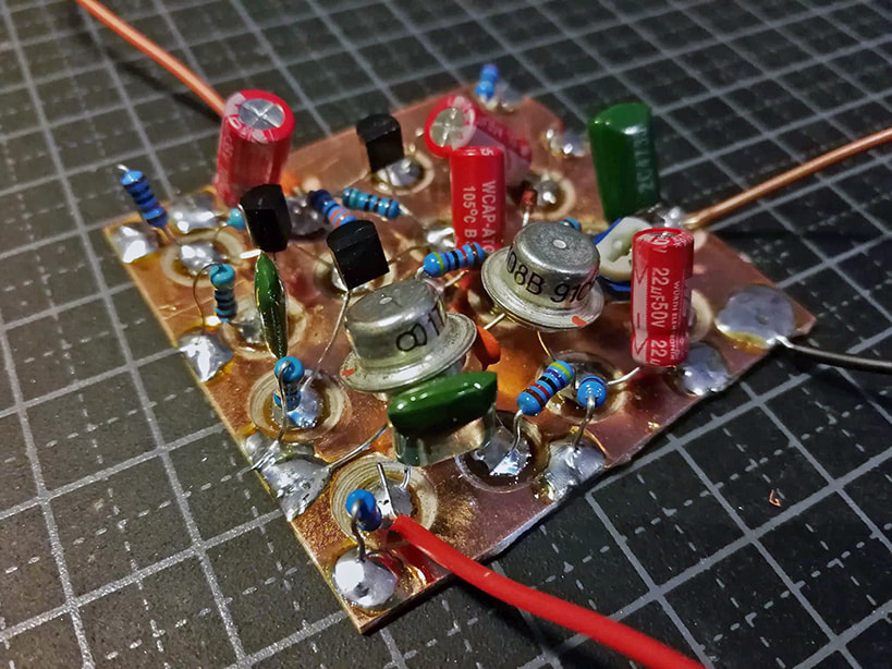
I try to keep the distance between the middle of the pads to around 8mm-13mm so that the components are tight together, but not too close that is becomes too fiddely to work with. After the pads are made I like to pre-solder all the pads - just fill them up with a decent amount of solder. Now the board is perpared and it's time to start soldering in the components. Cut the legs of the component alittle shorter (check the distance against the board) and bend the legs alittle to make small "feet". Reflow the solder of the pad and put the component in. Hold it and let it cool for a few seconds, then do the other side. As you go along there will often be several components connected to the same pad, and then it helps to apply some new solder to the pad when adding more components. I find that it's best to start in the upper left corner and work your way through the board from left to right. ​

SCHEMATIC TO LAYOUT

​Before preparing the board, it's a good idea to make a sketch of the board layout. Converting a schematic to a Manhattan style layout is generally very easy since the layout will closely reflect the schematic in most cases. Here's to the right is an example of a circuit, the LPB1 booster - a very simple transistor amplifier.

​The first thing you need to do is to identify and count all the common nodes (or "nets" as they are typically called in PCB software). This is how many pads we need to drill on the board. Don't count the ground connection, as it will be connected to the rest of the copperboard as the groundplane.
Picture
Manhattan style LPB1 layout
Picture
LPB1 schematic
Picture
I've marked the schematic for every pad needed for the board
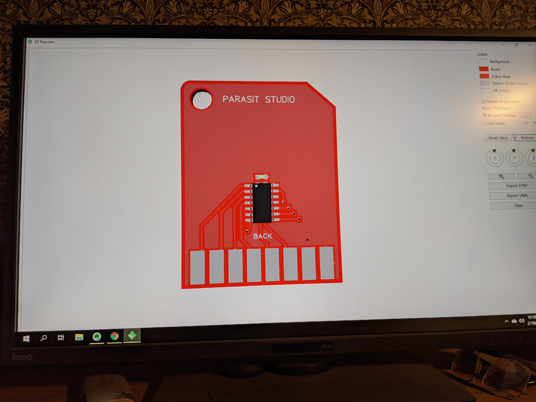
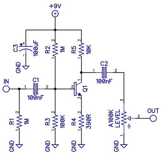
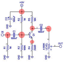
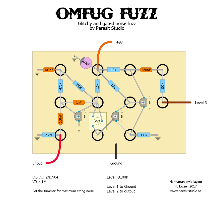
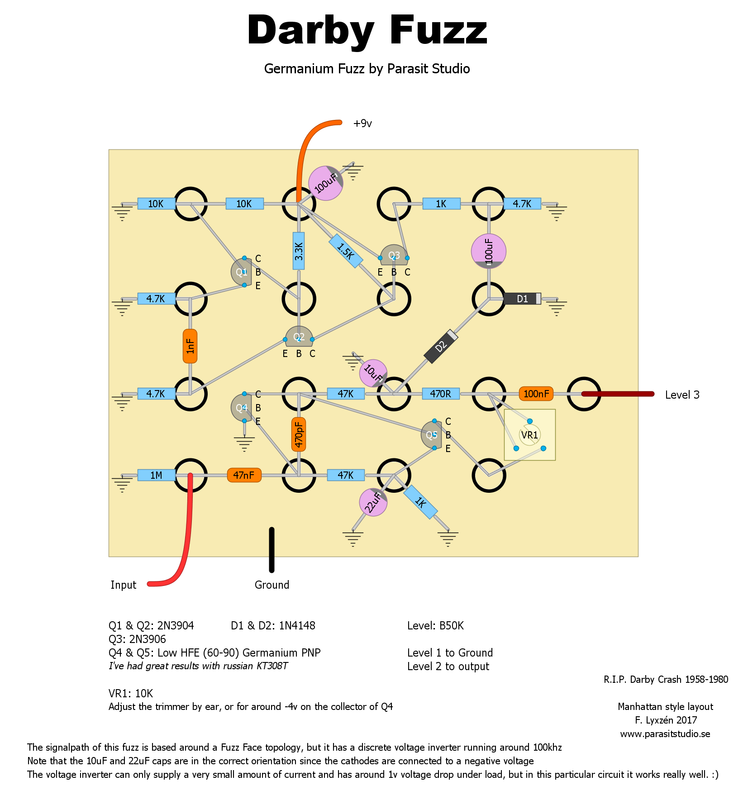
As you can see in this example, the layout follows the schematic with a few minor changes (just to have the pads lined up nicely). I normally just use pen and paper to make the layouts, but I wanted it clean and easy to read for this presentation.

Parasit Studio originals

I made two original designs specifically for Manhattan style of building. :)

OMFUG Fuzz

The Omfug is a gated and glitchy square wave one-knob fuzz. It's basically the preamp section of the Darkadiator (a discrete guitar synth) - a single gainstage followed by a schmitt trigger. I thought that the Omfug was a fitting name. A homage to the classic punk club CBGB's that was located in Manhattan... :)
I used very hot humbuckers. That's why the attack sounds so compressed.
Picture
OMFUG Fuzz Manhattan style layout

Darby Fuzz

Another one-knob fuzz. This is more of a ordinary fuzz loosely based on a fuzzface topology. It cleans up really well when turning your guitar volume down. I wanted to find a use for all those russian transistors that I have laying around so the signal path uses two germanium transistors. The rest of the circuit is a discrete voltage inverter, designed specifically for the manhattan style in mind so I could keep everything on the same board. You can play around with the values for the input and output capacitors for different bass response and thickness. The name is a homage to the band The Germs (because it's a germ-anium fuzz hehe...).
​​The discrete voltage inverter is not something I would recommend using for any other build style that can accomodate IC chips since an IC based voltage inverter will be far superiour in every way.
Picture
Darby Fuzz Manhattan style layout

CONCLUSION

Even through it might seem like a step backward, it's been really fun to make something different for a change. Expanding my bag of tricks, learning and challenging myself to come up with new stuff is what keeps this hobby fun and interesting for me. I haven't seen many pedalbuilder using this technique and I was inspiried to try it from a great HAM radio guy that I follow on youtube.

Check out his channel: 
https://www.youtube.com/user/w2aew/
6 Comments

The New Wave CV Generator released

9/26/2017

8 Comments

 
Here's a new DIY project that is a bit unusual. The "New Wave" is a Control Voltage Generator - two LFO's (Low Frequency Oscillators) in one box that you can use together with other pedals or synthesizers (with CV inputs) to modulate the sound of those devices (it doesn't do any sounds on its own).

Features:
  • Four different output modes:
    1. Square wave
    2. Triangle wave (or saw/ramp)
    3. Sample & Hold
    4. Sequencer (3 or 4 steps)
  • Slide - Smooth out the waveshapes (a.k.a. "portamento")
  • Switchable 5v or 9v operation and maximum output (Vpp)

It can be used with other Parasit Studio pedals such as the Into the Unknown, U-235 Suboctave Generator, Raygun Youth Fuzz, and many upcoming projects. Some old projects will also be updated with CV inputs.

The idea behind this project was inspired by modular synth design (let's bring some modular thinking to the pedal world!) and the name New Wave is inspired by the New Wave of punk and the New Wave of British Heavy Metal in the 80's.

The PCB is avaliable now in the shop
Picture
Picture

I have not made a proper demo yet, but here are a couple of examples.
The first prototype didn't have the slide and depth controls
The CV Generator is used from about 2 minutes in
I hope you like it! :)
8 Comments

The U-235 released!

9/11/2017

7 Comments

 
Here's a new DIY project that I have been working on for a while -
the U-235 Suboctave Generator.

In short, it's an analog monophonic octave down pedal.

I wanted to do something a bit different, so this pedal uses a CD4046 PLL to do the freqeuency dividing, insted of a D-flip flop that are typically used in analog octave down pedals. This allowed me to add a couple of fun features like the Detuned Mode and the CV input.

Here's a short demo (the fun part starts at about 2 minutes in...)
It will work best for guitar since the tracking gets alittle bit slower at the lower notes, but you can clean up the tracking by using the neck pickup. I also have found that it helps alot to palm-mute the strings alittle bit when playing the lowest notes.

I will not share the schematic for the U-235, so please don't ask for it. But when I have time I will try to write another part for the CMOS Workshop series that will explain how to set up the 4046 as a frequency divider so that you can breadboard it yourself and play around with it.

I hope you like it. :)
PCB avaliable now in the shop
Assembled pedals coming soon
Picture
U-235 Suboctave Generator PCB
In the last half of the demo I'm using the "New Wave CV Generator" (more info on that project coming soon) as a Control Voltage source, but you can hook up any LFO, from a synthesizer or another pedal.

..or why not build your own simple square wave LFO on a piece of veroboard and put it in the same enclosure? :)


Building tip: Make the input and output wires as short as possible. There's alot of high amplitude square waves going on inside the circuit and it can easily bleed into the clean signalpath, making it sound less clean than it's supposed to be. Never run the wires under/over the board. Just a small thing to keep in mind.
7 Comments
<<Previous
  • DIY GUITAR EFFECTS
    • Original Effects
    • Building blog
    • DIY Gallery
    • Stripboard layouts
    • Articles
  • SHOP
  • BUILD DOCS
  • ABOUT