PARASIT STUDIO
  • DIY GUITAR EFFECTS
    • Original Effects
    • Building blog
    • DIY Gallery
    • Stripboard layouts
    • Articles
  • SHOP
  • BUILD DOCS
  • ABOUT

CMOS Workshop Part 4: octave up

1/3/2017

18 Comments

 
It's time for another part of the CMOS Workshop series. :)
This part will be about octave up circuits (aka frequency doublers).
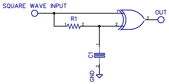
Picture
The easiest way to produce a digital octave up is by using a Pulse Generator circuit, also called a Edge Detector. It generates a pulse at every high-to-low and every low-to-high logic transition, thus doubling the frequency.

It's a simple circuit and what used for the Arcadiator. There are several ways to do this. Let's have a look at a few examples and start with the easiest way that require the least amount of components.

You can click on the images for a larger view.
Picture
The top row shows the square wave and the bottom row shows the pulses generated with the edge detector circuit

1. XOR gate (CD4070)

The CD4070 is ideal for this purpose and require very little extra components.
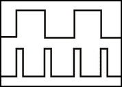
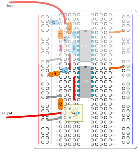
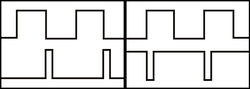
Picture
XOR pulse generator schematic
XOR logic: For the output to go high, ​both inputs needs to be at a different state

​By connecting our square wave to both inputs and delaying one of the inputs slightly, there will be a brief moment when the inputs are in different states. At this moment the output will go high, thus creating a short pulse wave at the output every time the input goes high or low.

The delay is made out of a simple RC filter. It will round out the square wave, so that it takes alittle longer for each transition to cross the switching threshold of the logic gate.

Lets try this circuit on the breadboard. Remember to always disable all the unused inputs.
Picture
1A
Picture
1B
Picture
XOR pinout and truth table
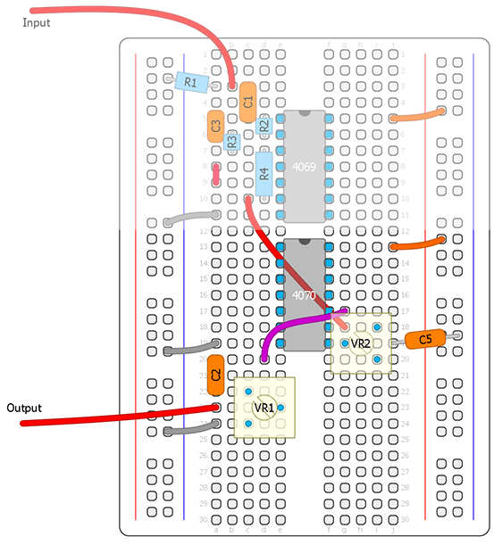
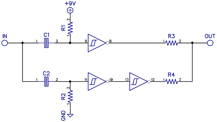
Here we can play around with different values for the RC filter. It will change the width of the pulses and the character of the sound. For C5 (C1 on the schematic) try a 4.7nF - 47nF value. For R5 (R1 on the schematic) try 10K-500K. In the 1B example I've replaced R5 with a trimmer and for convenience I chose another gate. The top greyed out part is the gainstage and schmitt trigger front end from the CMOS Workshop part 2 so you will have to check the other component values there.

Notice that the pulse width can get too narrow or wide for the octave up effect to work. As a rule of thumb you don't want the pulses to be too narrow because it will sound bad, and you don't want the pulses too wide because then it won't track properly on the entire fretboard.

If you don't have any CD4070 chip at hand you can use a CD4011 chip to homecook one XOR gate our of four NAND gates.

But what if you don't have that either?

​Surely you must have at least one CD40106 or a CD4093 chip laying around. We can use "Mickey Mouse Logic" that I have mentioned before to make four NAND gates out of four schmitt trigger gates by using diodes and resistors, then connect them together to form a XOR gate.
Picture
It's possible yes, but silly. The amount of components required is rediculous.
​There are other much easier ways if you want to use a schmitt trigger chip...  :)
Picture
NAND gates connected together for XOR logic
Picture
"Mickey Mouse logic" using schmitt triggers

2. Schmitt Trigger (CD40106 or CD4093)

With a schmitt trigger gate we can make a simple edge detector shown to the right. However, it's only producing a pulse each time the input goes high (or only the opposite), so it's not really what we want for an octave up effect. It basically just changes the pulse width (this is how Tim Escobedo's "PWM" works).

So how can we turn this little circuit into a frequency doubler? Simple, we just need two of these and one inverter. One edge detector for the negative edge, and one for the positive edge. Then we simply invert one of the pulse outputs and sum them together and we have a frequency doubler. :)
Picture
Schmitt Trigger Octave Up A
Picture
Schmitt Trigger Octave Up B
Picture
This circuit produces a negative going pulse at each transition from low to high at the input
If we connect the resistor to V+ insted of ground, the circuit will work the opposite
Picture
The pulse outputs of the two edge detectors
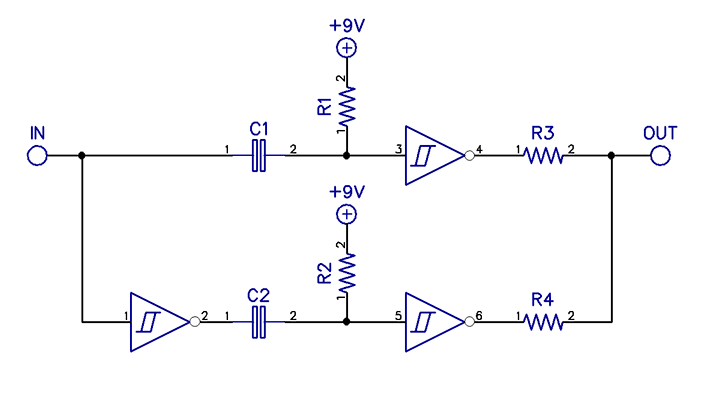
The B schematic is just another way of doing the same thing. I just moved the inverter to the input insted.
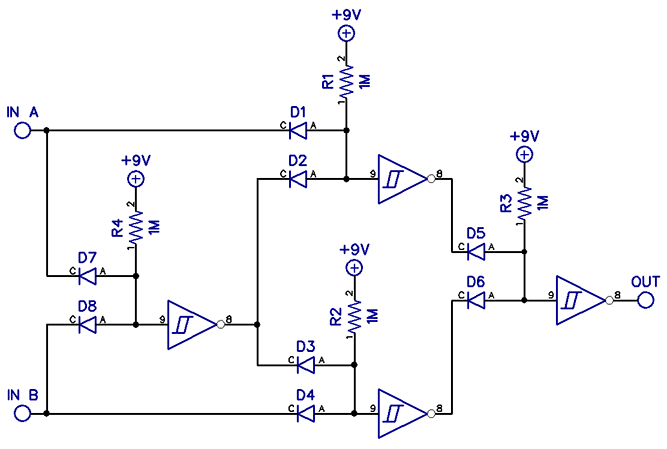
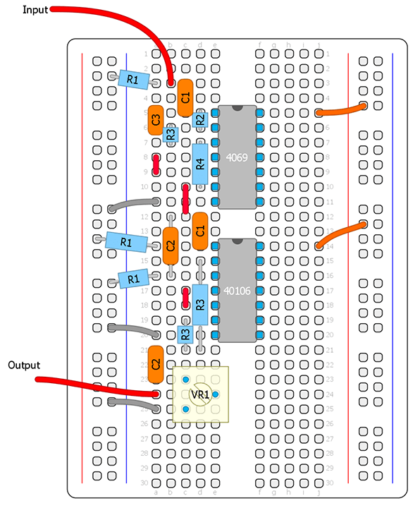
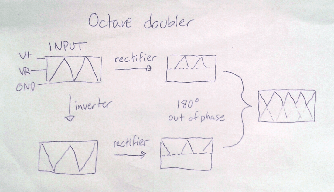
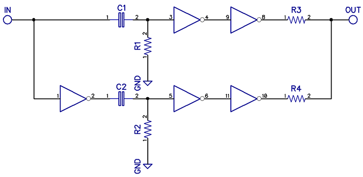
Lets put it up on the breadboard!
​C1/C2 = 10nF, R1/R2 = 47K, R3/R4 = 10K

Here you can play around with the R1/R2 resistor values for different pulse widths. This way of making a frequency doubler also has a couple of benefits over the XOR version. You can connect a LFO directly to R1 (or R2, or both) to modulate the pulse width. You can also switch in/out the second edge detector to toggle between octave up or a pwm sound, just like the Arcadiator.
Picture
Schmitt Trigger octave up with possible mods
Picture
Schmitt Trigger Octave Up A
In the last schematic I added an offset trimmer to the LFO input, which would probably be needed along with some attunement of the LFO voltage. Experiment! :)

3. Octave up using rectifiers

This is not really CMOS related, but I thought I'd just give a quick and crude explanation of how an octave up circuit works using rectifiers. It's probably the most common way of making an octave up circuit for guitar effects.

​Simply put, the signal gets split into two signal paths (one is being inverted), then two rectifiers (one per sinal-path) cuts off half the waveform and then both rectified signals gets summed together (so in a small way it resembles the schmitt trigger method).

​I won't go into any more detail about this method.  There's plenty to find out if you google about half wave and full wave rectifiers. A rectifier octave up circuit is what I'm using in both the Eagle Claw and Sidescroller Fuzz.
Picture
This shows a very simplified waveform to give you an idea of what is happening. Sorry about my crappy handwriting :P
Just as the schmitt trigger schematics showed, the inverter can be placed after one of the recitifiers insted if one of the rectifiers is cutting off the opposide side of the waveform.

4. NOT gate (CD4069)

There's one last version I would like to include in the article, similar to the schmitt trigger one, except that it uses regular inverters.
Picture
Octave up using five inverters / one CD4069
This version will only work with a prettly low value pulldown resistors since a regular inverter gate has no built in hysteresis to take advantage of. Use 4.7k resistors for R1/R2. To set the pulse width, play around with the cap values insted. When I breadboaded this I got good results using 150nF for C1/C2. The two extra inverters are there to clean up the pulses which looks kinda crude at the output of the first inverter, but it will work ok without them.

And last but not least, here's a video that shows the waveforms on a scope. The yellow line is our original square wave and the blue line is the pulse ouput from the edge detector circuit. I'm playing around with the pulse width, and as you can hear, it changes the sound from full to thinner and more nasaly sounding.

That's all I had for this part.
I've given some examples of how to make frequency doublers with edge detector circuits using at least 5 different CMOS chips (if you count the schmitt trigger variations). Which one you choose will probably depend on the rest of the circuit you are making. Maybe you already need a schmitt trigger chip in your circuit to do other functions, then example nr 2 is better because you will still have 3 gates left over (if using a CD40106) insted of adding an xor chip to only do one thing. Personally I prefer to keep the chip count as low as possible even if it adds more components. It usually takes less time to solder a few extra resistors and caps then having to solder another 14 or 16 pin chip (which also takes more space on the PCB). It's all about convenience.

As I've shown, there's usually several ways to do the same thing when working with CMOS. Remember that we're dealing with 1's and 0's, so no matter which chip/method you use it will basically sound exactly the same (granted that the pulse width is equal of course). Same goes for the octave down methods in the previous part. However, there is a clearly sounding difference between edge trigger or rectifier doublers, or PLL VCO frequency doublers  (as used in the Into the Unknown guitar synth) which I will cover in a later part.

But next part will be about oscillators and LFO's.
​We will breadboard some fun stuff, as I've promised :)
18 Comments
Fredrik Lyxzén link
1/8/2017 03:34:10 pm

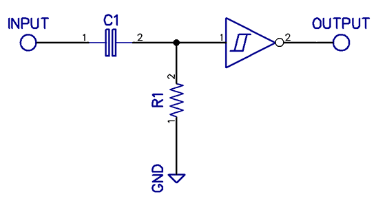
Some additional info on how the pulse generator in example 2 works: "With no changes occuring on the input, the 1M resistor to ground holds the input low and thus the output high. When a low-to-high logic transition is applied at the input, the front of the voltage step is capacitively coupled through the C1 and dropped onto R1 as a narrow low-to-high pulse. The output of the schmitt trigger pulses low in response and then returns high due to R1 holding the input at ground." Explanation quoted from Ray Wilson's book "Make: Analog Synthesizers" (with a minor tweak to fit the schematic shown here)

Reply
Sergio
1/13/2017 10:22:00 am

Very interesting. Thanks a lot.

Reply
casinon utan spelpaus link
2/9/2022 01:04:14 am

The entirety stays so proper with them! I'm glad that I selected them for my work! First-rate!

Reply
Staffan link
1/13/2017 12:21:39 pm

Hej! Jösses vilken trevlig läsning! Jag har byggt några pedaler på stripboard (fuzz/od/dist) från den eminenta sidan tagboardeffects.com, men haft lite svårt att hitta bra info om hur sakerna fungerar. Det finns väldigt mycket om elektronik, men jag har känt att det varit lite knepigt att knyta den informationen till audio, och att audio är ac har rört till det lite för mig.
Jag hade faktiskt tankar på att maila dig och be om lite tips om var man kan hitta bra info om elektronik som är lite mer relaterad till just pedaler. Hade helt missat dessa sidor!
Har några CD4049UBE (felbeställning) liggandes som kan komma till användning (utöver fuzz) och har precis testat att göra en oscillator av en schmitt-trigger (som av någon anledning var ojämn i oscillationen, ingen aning varför).
Äh, jag är glad att jag hittade dessa sidor. Uppskattar det du gör och hoppas att du mosar ut så mycket info du orkar.
Ha en bra helg!

Reply
Fredrik Lyxzén link
1/15/2017 03:59:36 pm

Hej Staffan!
Tack för kommentaren. Kul att någon faktiskt läser detta och uppskattar det. :) Jag började själv att bygga pedaler tack vare tagboardeffects som är en enormt bra resurs. Geofex.com är en bra sida men annars vet jag inte direkt någon så jättebra för att lära sig mer om elektronik/pedaler. Man får liksom leta runt plocka en bit här och där. Jag försöker dela med mig av det lilla jag själv kan, även om CMOS kanske är vanligare i synth världen. :) mvh / Fredrik

Reply
thehallofshields
1/16/2018 09:38:12 pm

Fredrik, how about a ::Part 5: Getting Started with the PLL::

Reply
Fredrik Lyxzén link
1/18/2018 04:34:52 am

Yes, i've been about doing a part about the PLL. Maybe when I have time (always the issue) I'll try to write up something. :)

Reply
Jon B
3/11/2018 08:45:58 pm

These are super helpful! I've breadboarded a couple circuits based on some of this and they sound so cool. Thanks man!

Reply
Reece
4/13/2019 05:42:52 am

Just read through all these articles and they are so handy. I have breadboarded the octave down and up and was wondering how I would go about outputting them both and the original square wave from the 4069?

Reply
Fredrik Lyxzén link
4/17/2019 03:32:52 am

Hi Reece,

You can blend the outputs together using 100K resistors from each output, or use a B250K potentiometer and take one output to pin 1, the other output to pin 3 and the summed output from pin 2

Reply
Tadashi Takahashi
3/10/2020 04:19:50 pm

Hello. I have a question about Schmitt Trigger octave up with possible mods in your article. What lfo circuit should be connected to the lfo input? I want you to tell me specifically. I tried various things myself, but I could not do it well.

Reply
Fredrik Lyxzén link
3/11/2020 06:31:57 am

Hi,

I used a signal generator (using a triangle shape) as an LFO when breadboarding, but it was a long time ago I played around with that specific idea, so I don't remember the details. You probably need to both ajust the amplitude of the LFO going in (with a voltage divider), then offset the voltage aswell to find the sweet spot with a good response.

Reply
Mariano segat link
5/5/2020 09:38:11 pm

Awesome articles! I wanted to ask you this kind of questions, but I thought it could bother you. So instead I just looked up the chips of you use in your pedals in google to study different circuits, and looking up in google I found this article that you made explaining everything in detail applied to gutiar pedals. Funny thing. I am really waiting for the PLL article. We don't deserve you.

Reply
Cole U McCray
5/9/2020 09:59:01 pm

I highly recommend the book by Nic Collins titled: "Handmade Electronic Music" a free .pdf can be found by searching. ..
There is a whole chapter on the 4046 PLL chip.
This book has helped me immensely. :)

Reply
Steve Fdez
11/16/2020 05:07:02 pm

Hi! Just wanna say WOW!! Great articles! I been enjoying all of them and of course learning a lot of how CMOS are really working. I hope you'll get the time/energy to continue making more content of this kind.
Well.. just wanna say THANK YOU!

Reply
Fredrik Lyxzén link
11/18/2020 03:47:18 am

Hi Steve,
Thank you for the comment. I'm glad that you have appreciated the articles. :) Cheers / Fredrik

Reply
kira
12/15/2020 08:09:59 pm

hi ive been messin witch chips for years cant believe it took me so long to find your content!! would be great if you made an article on oscillators. i know how to make them work but your insight on them would probably be great. thanls!

Reply
Guillemdc link
9/14/2021 04:23:33 am

Hi Fredrik,

To begin with, thanks a lot for this workshop. It's amazing!
However, I'm having trouble getting the octave up to work using a 40106. I'm using your same circuit but I get almost no sound. Could it be because my chip is the buffered version? I get a great fuzz from the 4069UBE but nothing from the 40106BE

Cheers!

Reply


Leave a Reply.

  • DIY GUITAR EFFECTS
    • Original Effects
    • Building blog
    • DIY Gallery
    • Stripboard layouts
    • Articles
  • SHOP
  • BUILD DOCS
  • ABOUT