PARASIT STUDIO
  • DIY GUITAR EFFECTS
    • Original Effects
    • Building blog
    • DIY Gallery
    • Stripboard layouts
    • Articles
  • SHOP
  • BUILD DOCS
  • ABOUT

Manhattan style pedalbuilding

11/2/2017

6 Comments

 
The "Manhattan style" is a very old method of circuit construction. It's especially popular among radio amateurs for high frequency circuits because it has a solid ground plane that helps to reduce interference and noise.

​It's also a fun way to build simple discrete circuits. :)

​Pros:
  • Fast build time (at least compared to etching boards)
  • Easy building and schematic to layout conversion
  • Great for quiet noise free-builds (superior to stripboard, perfboard and tagboard in this respect)
Cons:
  • Doesn't suit IC chips
  • Only good for smaller less complex circuits
Picture
The Darby Fuzz
Some people would probably not agree with the disadvantages I listed since I've seen people go crazy with complex build using IC chips and even SMD components on Manhattan style builds.

BUILD PROCESS

To build Manhattan style you need a copperclad board. It only needs to be a one-sided copper layer. The first step is to make small cutouts in the copper for the component pads and cut the board to a good size (to fit the enclosure that you want to use). I use a bench drill with a circular drillbit to make small  "islands" in the copper. Just be careful so you don't drill all the way through. It's a good idea to use a multimeter to check that all the pads are not conducting to the rest of the board (which will be connected to ground). Another common method that doesn't require a drill is to cut out small pieces of copperboard (from another piece of board) and glue them onto the main copperboard to serve as component mounting platforms.

​
I'm using a "diamond hole drill bit" like this one (the 8mm one).
I try to keep the distance between the middle of the pads to around 8mm-13mm so that the components are tight together, but not too close that is becomes too fiddely to work with. After the pads are made I like to pre-solder all the pads - just fill them up with a decent amount of solder. Now the board is perpared and it's time to start soldering in the components. Cut the legs of the component alittle shorter (check the distance against the board) and bend the legs alittle to make small "feet". Reflow the solder of the pad and put the component in. Hold it and let it cool for a few seconds, then do the other side. As you go along there will often be several components connected to the same pad, and then it helps to apply some new solder to the pad when adding more components. I find that it's best to start in the upper left corner and work your way through the board from left to right. ​

SCHEMATIC TO LAYOUT

​Before preparing the board, it's a good idea to make a sketch of the board layout. Converting a schematic to a Manhattan style layout is generally very easy since the layout will closely reflect the schematic in most cases. Here's to the right is an example of a circuit, the LPB1 booster - a very simple transistor amplifier.

​The first thing you need to do is to identify and count all the common nodes (or "nets" as they are typically called in PCB software). This is how many pads we need to drill on the board. Don't count the ground connection, as it will be connected to the rest of the copperboard as the groundplane.
Picture
Manhattan style LPB1 layout
Picture
LPB1 schematic
Picture
I've marked the schematic for every pad needed for the board
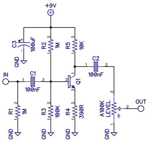
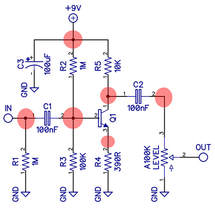
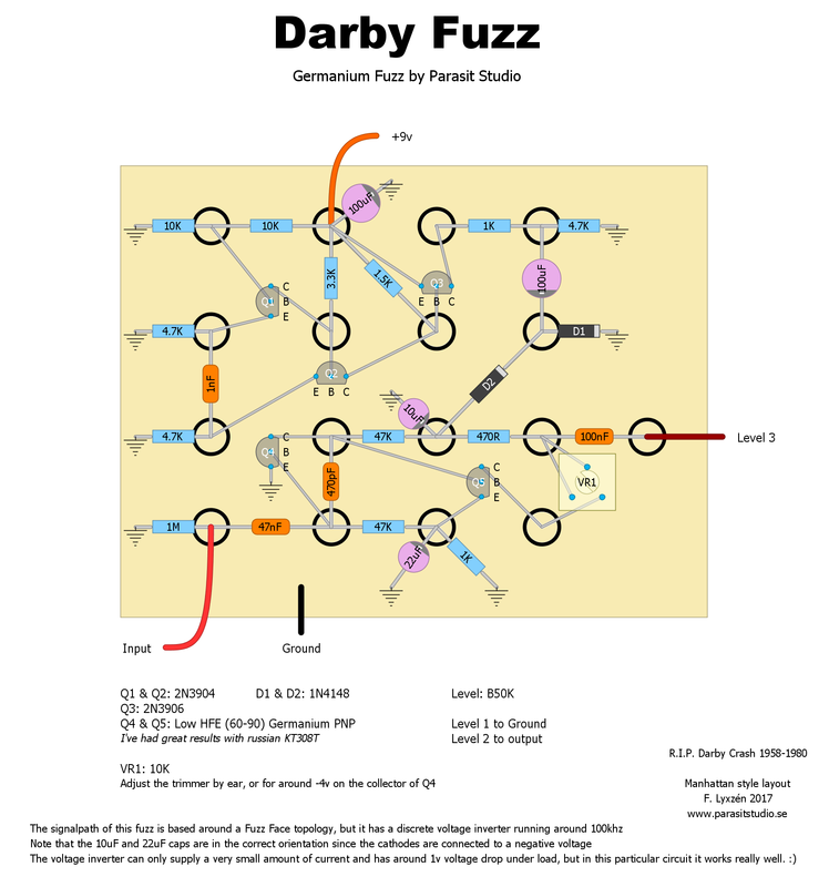
As you can see in this example, the layout follows the schematic with a few minor changes (just to have the pads lined up nicely). I normally just use pen and paper to make the layouts, but I wanted it clean and easy to read for this presentation.

Parasit Studio originals

I made two original designs specifically for Manhattan style of building. :)

OMFUG Fuzz

The Omfug is a gated and glitchy square wave one-knob fuzz. It's basically the preamp section of the Darkadiator (a discrete guitar synth) - a single gainstage followed by a schmitt trigger. I thought that the Omfug was a fitting name. A homage to the classic punk club CBGB's that was located in Manhattan... :)
I used very hot humbuckers. That's why the attack sounds so compressed.
Picture
OMFUG Fuzz Manhattan style layout

Darby Fuzz

Another one-knob fuzz. This is more of a ordinary fuzz loosely based on a fuzzface topology. It cleans up really well when turning your guitar volume down. I wanted to find a use for all those russian transistors that I have laying around so the signal path uses two germanium transistors. The rest of the circuit is a discrete voltage inverter, designed specifically for the manhattan style in mind so I could keep everything on the same board. You can play around with the values for the input and output capacitors for different bass response and thickness. The name is a homage to the band The Germs (because it's a germ-anium fuzz hehe...).
​​The discrete voltage inverter is not something I would recommend using for any other build style that can accomodate IC chips since an IC based voltage inverter will be far superiour in every way.
Picture
Darby Fuzz Manhattan style layout

CONCLUSION

Even through it might seem like a step backward, it's been really fun to make something different for a change. Expanding my bag of tricks, learning and challenging myself to come up with new stuff is what keeps this hobby fun and interesting for me. I haven't seen many pedalbuilder using this technique and I was inspiried to try it from a great HAM radio guy that I follow on youtube.

Check out his channel: 
https://www.youtube.com/user/w2aew/
6 Comments
Anders
11/6/2017 02:03:52 am

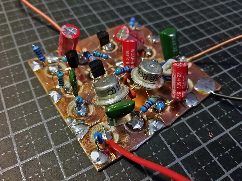
This is very cool. I think I'm going to try this since I also have loads of these soviet germaniums laying around. One question; whrere do you get those sweet red electrolyctics?

Reply
Fredrik Lyxzén link
11/6/2017 01:13:50 pm

I got the red electrolytics from digikey. The brand is called Wurth. :) Just wanted to match my red Arcadiator PCB's. :P

Reply
lynne link
3/22/2018 10:52:58 pm

Dear Sir/Madam:

Have a nice day!


This is Shenzhen Found Printed Circuit Board CO.,LTD


We produce is PCBs. Including Metal Core PCB.PCBA,Flex PCB,


High Frequency PCB,SMT Stencil and FR4 PCB.


Our PCB UL NO. is E361831.


Found Circuit, one professional Printed Circuit Board Manufacturer


in China, can supply PCB with high quality and pretty competitive


price to you. And we have passed ISO9001,ISO14001,TS16949,SGS


and UL certificates,hope to have a cooperation with you.


If you are interested in our products, please contact us.


Please give my best wishes to you and your family.

Reply
Alina
9/17/2018 02:06:23 am

Hello friend,

We are a professional PCB and PCBA factory,we always promise very good quality PCB&PCBA with reasonable price to our customers.
If you have any need, please send me GERBER files(maybe including BOMs)!

Many thanks!

Reply
Andreas
11/29/2021 09:30:21 pm

Yor link for the Drill bit is broken, just to let you know. Cheers, Andreas.

Reply
EDU BackLinks link
2/25/2023 11:52:56 pm

I really like your take on the issue. I now have a clear idea on what this matter is all about..

Reply


Leave a Reply.

  • DIY GUITAR EFFECTS
    • Original Effects
    • Building blog
    • DIY Gallery
    • Stripboard layouts
    • Articles
  • SHOP
  • BUILD DOCS
  • ABOUT