PARASIT STUDIO
  • DIY GUITAR EFFECTS
    • Original Effects
    • Building blog
    • DIY Gallery
    • Stripboard layouts
    • Articles
  • SHOP
  • BUILD DOCS
  • ABOUT

Active Baxandall tonestack

9/29/2014

13 Comments

 
EDIT 2014-09-29
I added a PCB layout to the bottom of the post.


Here's a nice active Baxandall qualizer that I designed. Originally I did a layout for a schematic called "Bax in a box" (google it and you'll find it) that worked ok, but it was just "semi-active". The dual op-amp was just acting as a buffer and a make-up gainstage, so this is my take on an improved truly active version.

 You can put after your favourite fuzz or whatever, or just in a stand alone box.
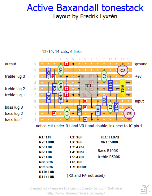
Picture
active_bax_eq_pcb.pdf
File Size: 79 kb
File Type: pdf
Download File

13 Comments
Jim
1/25/2015 03:40:03 pm

What does VR1 do?

Reply
Fredrik Lyxzén link
1/25/2015 04:43:38 pm

VR1 sets the gain of the first op amp stage and acts like a volume pot. Set the bass and treble controls at noon and use VR1 to match the volume with the bypassed signal. The trimmer could also be replaced with a pot if you want the control outside the box. Recommended if you are using it as a stand alone effect.

cheers / Fredrik

Reply
Jim
1/25/2015 11:23:20 pm

Thanks, I can think of a bunch different uses for this.

Juan
4/1/2015 11:36:10 pm

Hello Fredrik,

Thank you for sharing this circuit.
I have a question regarding the mids. I tried the "passive Baxandall" (didn't like the gain loss) and via a rotary switch I was able to change the value of a certain cap in order to modify the mids. The schematic for this one is slightly different, and I can't tell which cap I can tell change to do this. I woukd really appreciate if you could help me wiyh this.

Cheers, Juan

Reply
Fredrik Lyxzén link
4/3/2015 02:02:14 am

Hi Juan
I'm sorry but I don't know how to change the mids in this version of the baxandall tone-stack. It was a long time ago I played around with the bax circuit so I will have to read up on it again. I'm however ill with the flu right now, otherwise I would research a answer for you. It might be better if you asked in the diystompboxes forum for now. Could you possible send me the schematic for the passive version and explain which cap you changed, and I will have a look at it when i'm feeling better? Maybe it can be converted into an active circuit. cheers / Fredrik

Reply
Brad Hill
4/16/2016 08:21:29 am

Thanks for posting this vero layout! If I want to replace the trimmer with a pot, would the lug designations be: (1=d15, 2=e13, 3=f15) or the other way around (i.e. 1=f15, 2=e13, 3=d15)?

Reply
Fredrik Lyxzén link
5/5/2016 01:25:21 pm

Hi Brad,
Sorry about the slow reply. The post notification had ended up in my junkmail folder. Well, better late than never..

I can't really answer your question. You will have to use trial and error to find the right designation. I recommend using alligator clips to try stuff like this. They are great. :) Cheers / Fredrik

Reply
Brad Hill
5/5/2016 04:09:51 pm

No problem! Thanks for getting back to me. I actually built the circuit and took a guess on the volume pot. Fortunately, I guessed right and the volume pot works in the familiar "Full Clockwise = Full Volume" when Lug1 connects to d15 and Lug3 connects to f15.

Fernando
6/30/2017 05:11:10 pm

Does it work for bass?

Reply
Jonathon Yi
8/18/2017 09:50:35 am

Great layout! I like how compact it is!

I built two of these on separate occasions and have noticed both of them will pop very loudly when engaging the circuit.

Anyone else have this issue? I'm assuming my 1uf output caps are bleeding a lot of DC? Maybe I can try an electro?

Reply
Fredrik Lyxzén link
8/18/2017 10:43:41 am

Hi Jonathon,

Try adding a 1M resistor from the input to ground. You can also try adding a 100K resistor from the output to ground. That should help eliminate any popping sound when using this as a stand-alone box. :)

Cheers
/ Fredrik

Reply
agschaid
1/8/2018 12:18:31 am

Hi there,
first of all: thanks a lot for that circuit.

What exactly is the advantage of such an "truly active" design (in comparison to a semi-active one)? I suspect less noise, correct?

Can I still plug the resistor/capacitor values of the tonestack in a simulation software (like the Duncan Tonestack Simulator) and get meaningful results?
If so: what would be the source resistance? (guess I'd have to add a series resistor in front of the tonestack to establish some defined resistance, right?)

Reply
Willy
10/6/2019 11:24:02 pm

Works great! Used it to replace the tone section of a Madbean Boneyard vero.

Reply


Leave a Reply.

    vero layouts

    All the layouts are Verified unless noted.

    Archives

    February 2018
    October 2017
    September 2015
    June 2015
    April 2015
    February 2015
    December 2014
    November 2014
    October 2014
    September 2014
    August 2014
    July 2014
    June 2014
    May 2014
    April 2014
    March 2014

    Categories

    All
    Amps
    Boosters
    Chorus
    Compressor
    Filters
    Fuzz
    Noise
    Octave Down
    Overdrive & Distortion
    Phaser
    Pro Audio
    Ringmods
    Tremolo
    Utility

    RSS Feed

  • DIY GUITAR EFFECTS
    • Original Effects
    • Building blog
    • DIY Gallery
    • Stripboard layouts
    • Articles
  • SHOP
  • BUILD DOCS
  • ABOUT