|
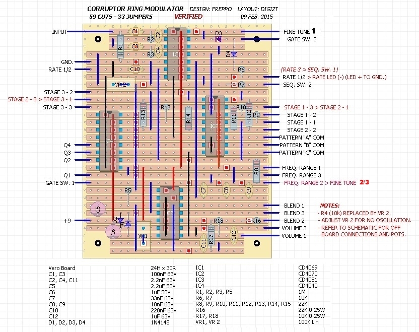
Another original ring modulator design. This is a much more complex version of the original Corruptor ring modulator. Insted of a ordinary oscillator we have a sequencer for the carrier frequency: 8 different steps that can be configured in alot of different ways. It can also be used as a stand-alone sequencer "synth" or a square wave fuzz and it can also do regular ringmod sounds. A perfect project for those who love off-board wiring.. :P The controls are: VOL: overall output volume MIX: this blends between ringmodulated signal and straight square wave fuzz FREQ: this is for fine tuning the frequency RATE: this controls the speed of the sequencer Rotary switches x3: these control the order of the sequencer steps Stages switches x3: these bypasses different steps in the sequencer SEQ switch: this turns on/off the LFO that drives the sequencer (does not turn of the oscillator) RANGE switch: this toggles between 3 different frequency ranges GATE switch: This turns on/off the gate. In the off position you have a free running sequencer Vero layout by Dino. Thanks!
3 Comments
GREG
5/16/2015 03:18:23 pm
hey hey! I'd love to build this bad boy but I am not entirely sure where to source the rotaries. Any suggestions? 5/16/2015 06:38:02 pm
Hi Greg
Sebastien
3/23/2016 02:45:45 pm
hello Frederik, after finish with sucess the "into the unknown" pedal which is so fun !!! i try to finish this one. my problem is i'm not sure about connexion of 9 v connexions on the rotary switch. Leave a Reply. |
|||||||||