|
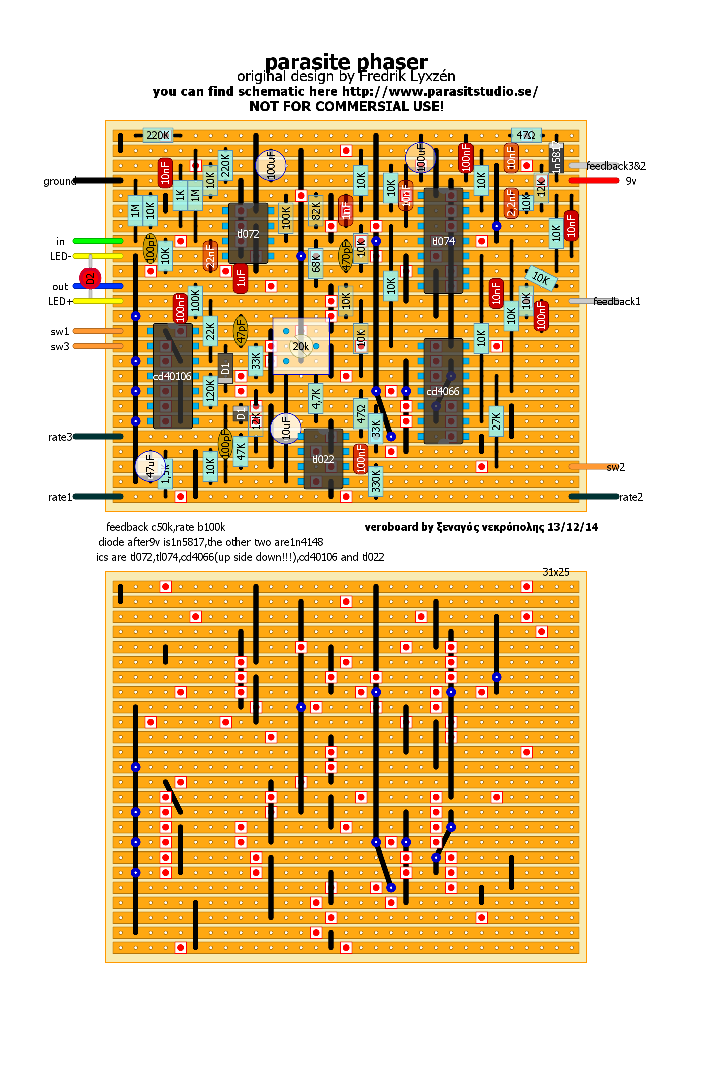
Update 2014-12-23: Savvas @ the tagboardeffects forum was kind enough to share a verfied vero layout for this one. :) Thanks alot! Original thread here. I added the vero layout to the bottom of the post. Here is a new original design that I have been working on for some time. It's a Pulse Width Controlled phaser that uses a CMOS switch as variable resistors. The main advantage to this approach is that you don't need to match JFET transistors or LDR/Vactrols. I hope you like it! :) Read about my progress, build reports, possible mods ect: http://www.diystompboxes.com/smfforum/index.php?topic=108823.0
29 Comments
John
12/2/2014 11:02:54 pm
Please, please post a vero layout for the Parasite Phaser. Thank you so much for your site. 12/25/2014 01:33:06 am
Hi John
clockman
8/10/2015 01:58:52 am
just finished the vero layout. Verified. works very well, has a small drop in overall volume compared to bypass signal. Great design, thank you so much for offering your work to the public. 9/21/2015 10:08:01 am
hi Fredrik, 9/22/2015 11:59:49 pm
Hi George, 9/23/2015 01:21:36 am
Hi Fredrik,
John
9/23/2015 05:59:53 pm
Is the double link (blue circle) at the very bottom supposed to be connected to another link, or is that a mistake. Thanks
John
9/24/2015 12:03:48 pm
Disregard my previous post. I just built it and it sounds fantastic. No volume drop on mine. I used 470k in place of 330k for slower speeds. 9/24/2015 03:42:52 pm
Sorry that I did not reply earlier.. busy day. :) I'm glad to hear that you like it. :) cheers! / Fredrik 1/26/2016 10:29:24 am
Hi Equis,
Equis
1/30/2016 08:35:13 am
Thanks for the reply!!! It is really annoying the ticking. I built it in a PCB .
equis
1/30/2016 09:13:27 am
i couldn't solve the problem yet. It is a really good sound pedal , Im going crazy! 1/30/2016 03:21:47 pm
Hi Equis,
Aisha
10/2/2016 04:57:53 pm
I have built the etched PCB version. Great-sounding phase! The ticking is very hard to get rid of. I had best results with a TL022 for IC5. I originally had a TL062 in there but the ticking was madness. The rate seemed slower with the TL022. I tried 330k, 470k and 680k resistors with both op amps. The variation seemed more extreme with the TL062. I like the rates I can get with the TL062 but with that extreme ticking, I ended up sticking with the TL022.
Steven
2/11/2016 05:37:51 pm
Any chance we can get a full version of the artwork on the pedal? 3/9/2016 03:25:45 am
Hi Steven,
timothy
3/9/2016 05:34:01 pm
I built the corrupter v1.1 and the fuzz section works and sounds really good but there is no ring modulator sound. the frequency control does not work. I used a CD7040BE instead of a CD7040 could that be the issue??? 3/14/2016 06:21:51 am
Hi Timothy,
Serhat
9/25/2019 03:08:43 pm
hello I did the signal as shown by downloading the engraved pbc version of the parasite phaser from your site but I have a problem adjusting the trimpot phaser what causes the bad stone phaser circuit to receive a manual phaser sound similar to the manual phaser circuit? I think the integration of Tl074 is broken, why can't I get automatic phaser sound? I used 1 uf 16 volt electrode capacitor instead of 1 uf on the output, could this be a problem?
Bonginator
2/4/2023 03:11:46 am
Dope phaser, Freppo u r king. thanks for sharing 2/7/2023 03:47:46 am
All your hard work is much appreciated. Nobody can stop to admire you. Lots of appreciation. 2/11/2023 01:16:35 pm
I wanted to thank you for this excellent read!! I definitely loved every little bit of it. I have you bookmarked your site to check out the new stuff you post. 2/25/2023 11:54:56 pm
Friend, this web site might be fabolous, i just like it.
Michailovic
4/24/2023 11:37:53 am
Hello, Great phaser. However it's not exactly unity when engaged. How would I tame it down to not boost the signal when engaged? 11/30/2023 03:10:03 am
At times, we need to invest a ton energy to locate the working way. This is extraordinary stuff. I love the manner in which you utilized the syntax on this post. Cool much appreciated 4/18/2024 05:49:20 pm
Some sort of clean kitchen is necessary to lower micro organism contamination. Seeing that, the types of surface like kitchens utilized frequently to ready our most liked dishes, and and so everyone ought to be more very careful about trying to keep it clean in order to avoid health risks. And, besides by frequent cleaning, but by means of deep cleaning the kitchen surfaces can prevent the spread connected with virus in addition to bacterias. Even so, it is required to include proper know-how about computers cleaning instruments. Leave a Reply. |
|||||||||