|
Here is a small utility board - a simple buffer followed by a phase inverter. You can take the output from either stage. It can be very useful if you are adding a clean blend to a circuit that is inverting the phase. 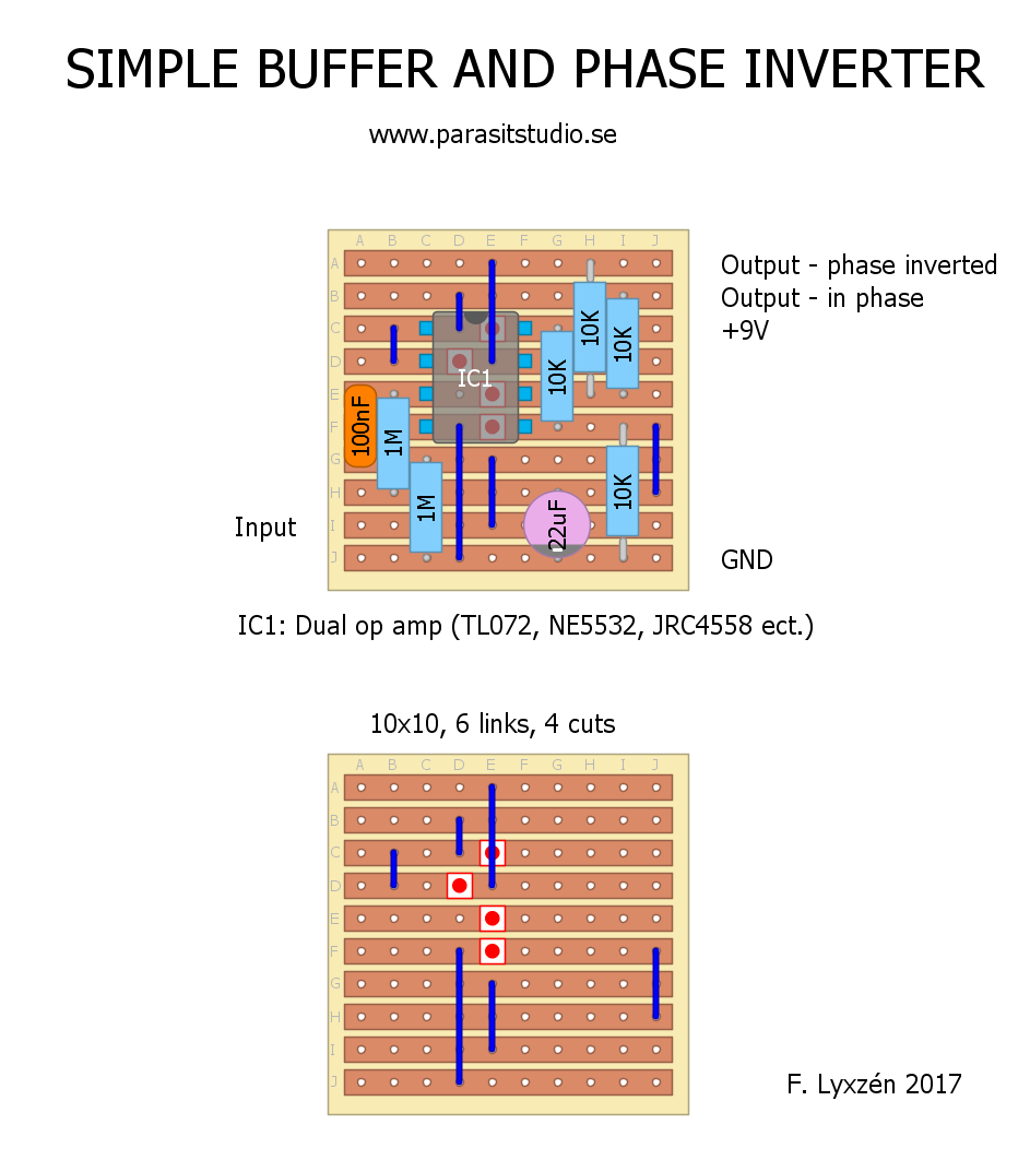 I recommend putting this in front of your main effect, but keep in mind that not all effects will respond the same with a buffer in front. I didn't include polarity protection, DC filtering and an output capacitor since this is meant to be used together with another effect (not stand alone). 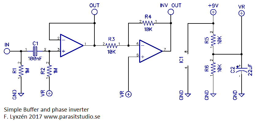
36 Comments
Michael
2/12/2018 05:14:53 pm
Hi, I built this and it seem to work just fine. It took me two hours of troubleshooting until I read your last remarks though :) Is it possible to use this at the end of a pedal chain before a last splitter? And what value cap would you choose for the output cap? 2/13/2018 01:40:58 am
Hi Michael,
Michael
2/13/2018 09:07:28 am
That was exactly what I wondered, thanks a lot!
Sebastian
7/27/2018 07:31:01 am
Hallo Michael, 9/27/2018 07:05:56 am
Yes, it should work fine with 12v. Just remember to add an output capacitor (any value 100nf - 10uF will work. Negative side to the output).
Marcus
2/8/2019 08:39:45 am
Hello. Thank you for this layout. Very good to find this. I have one more question. Is it possible to use your layout as dual invert buffer? because i have a stereo effect with two outputs, bouth out of phase with around 200k output impedance. Thats why i'm looking for a dual buffer with invert. 2/8/2019 11:45:32 am
Hi Marcus,
Marcus
2/19/2019 12:34:34 am
I did it. But the signal is clipping. Is it normally with this circuit? 2/19/2019 01:03:41 am
It should not be clipping unless you have a very hot signal. In that case you need to attenuate the signal before the input with a voltage divider, or run the buffer/inverter at a higher voltage (18v)
krabasti
2/10/2019 12:52:28 pm
Hello Fredrik, thanks for your quick reply. i just built this Buffer and really like it, but I've noticed a really odd issue that I can't figure out. When I plug my Guitar and turn up the volume knob i get noticeable noise. If I turn down the volume the noise goes away. I've tried power supply as well as battery with the same results. What can i do?
Marcel
10/7/2019 03:14:36 am
Is it possible to use this buffer (tl072) with 10 Mohm resistor for higher input impedance?
Marcel
10/8/2019 01:55:37 pm
or maybe with 3 Mohm. which resistors i have to change, R1 and R2?
Wallace
4/11/2020 10:49:15 am
Hello Fredrik,
Christopher Stelloh
8/22/2020 11:10:39 am
Hey there - question on this build - sorry if this is an old topic - but regarding the in phase and inverted phase outputs - I am planning on building this into a parallel loop mixer. I would like to make the phase inversion switchable. Would I do this with an SPDT on-on toggle, and if so, do I connect each of the phase outputs to an outer lug of the toggle, and connect the middle lug to the next circuit? Thank you for any help or insight you might have.
Chris Stelloh
8/22/2020 03:10:27 pm
Actually - I think I found a usable layout for an op amp parallel mixer that also has a switchable phase inverter in the circuit. I'll check back in if my tweaks to the design don't work out - I had to piece together a couple of different cap values since this build will be for bass guitar.
Angers
8/25/2020 09:32:45 pm
May I ask what the VR in the diagram stand for? 9/1/2020 05:02:26 am
It stands for Voltage Reference (also usually called "Vref"). It's a voltage divider (R5 and R6) that you need when using single supply operation (the capacitor will decouple/stabilize and filter the VR rail), so that the signal can bias/center around half the supply rail (4.5v in this case) for a maximum swing.
Vim
3/21/2021 08:17:56 am
Hi if I want to use 15 v positive and negative can it be used. I have a centre tap too so how can that be used. Thanks 3/22/2021 05:48:57 am
Yes, it can work with some small modifications to the layout.
Vim
3/25/2021 01:43:57 am
Hi fredrick much appreciated any chance of a small picture please😁
Jens Wellendorph
8/22/2021 09:34:42 am
Hi Fredrik. Thanks for your great work, hope you get by in these Covid-times. Is it it a simple matter of changing 1 or 2 resistors to get the phase inverter boosting signal with 10 - 16 db ? I need that to level up active magnetic PU's with Piezo in a mix-of-2-worlds guitar I've modified. Thanks :) ((I've left a few bucks as donation, I lived from being soundman for 20 years and can really see the bad effect on that branch)) 8/23/2021 11:01:29 am
Hi Jens!
Jens Wellendorph
8/23/2021 12:53:56 pm
Thank You, Fredrik. If I get it, then I put a 100K resistor as R4 to get 10db? But only on the reversed output - will the in-phase output then be 0? Or can I put 10k in front and 100k in feedback and get +10db, the same as reversed output? 8/27/2021 07:12:43 am
Yes, if you put a 100K resistor as R4 you will get a gain of 10. Just be careful that you don't clip the signal with too much gain. The in-phase output will still be at 0 gain (unity). The non-inverting opamp doesn't work the same way as the inverting opamp however, so you can't put a 10K in front and 100K in the feedback. I recommend that you check out the RST academy youtube video on opamps to understand how to set up the gain for a non-inverting opamp. It's not difficult, but too much to explain here. Cheers
Chris Wilson
9/3/2021 12:44:35 pm
Hi, 9/6/2021 01:25:31 am
Hi Chris,
Chris Wilson
9/13/2021 03:26:49 pm
I meant could you have both outputs in the same phase, not one in and one out. I've sourced another design since though that does it, thanks anyway.
Vincenzo
9/25/2021 05:45:46 am
Hi Fredrik, thanks a lot for this circuit! I wanted to build this to add a parallel fx loop to my pedalboard: http://tagboardeffects.blogspot.com/2012/02/split-n-blend.html and, as you'll see, this one behaves strangely with pedals spotting reversed polarity. That's why I wonder if your buffer 'n phase inverter can be daisy chained to the parallel efx loop in a single enclosure as follows:
Björn
12/8/2021 12:23:32 am
Looks neat! If I want to build a clean blend pedal with the possibility of phase inversion, do I connect the input of your circuit to the send of the blend? Or how would I connect the two circuits? Thanks in advance
Gilles
3/21/2022 07:44:38 am
Hello, is it possible to make this powered with +48V ?
Mihkel
6/13/2022 07:14:48 am
Hi, i built this inside a ab loop switcher. Now every time i press the loop switch. It makes a loud audible click. How would i fix this? 6/14/2022 10:58:06 pm
Hi Mihkel,
Hi Fredrik, big fan of what you do. 6/30/2023 11:45:53 am
Hi Randy!
Joseph
7/12/2023 09:54:17 pm
I recently built a JFET splitter and would like to use the bones of this circuit to make one of its outputs phase invertable. However, my splitter is already buffered, and experience has shown that stacking buffers back-to-back is generally bad idea. That in mind: could I chop anything out of your circuit to make it a bufferLESS phase inverter? If so, what? Leave a Reply. |
vero layoutsAll the layouts are Verified unless noted. Archives
February 2018
Categories
All
|
 RSS Feed