|
EDIT 2014-10-20 I added a soundclip. Notes: for this clip I had increased the 15K resistor (to the right of IC4) to 33K to lower the effect depth (I found it too wobbly), and I increased the 33K resistor to 47K to keep unity gain. This is as fast as this phaser goes, so it would probably be a good idea to mod the LFO secion aswell to increase the range. The wave-shape could also be better... but this is how it is without too much changes to the original schematic. DIY phaser from ETI. 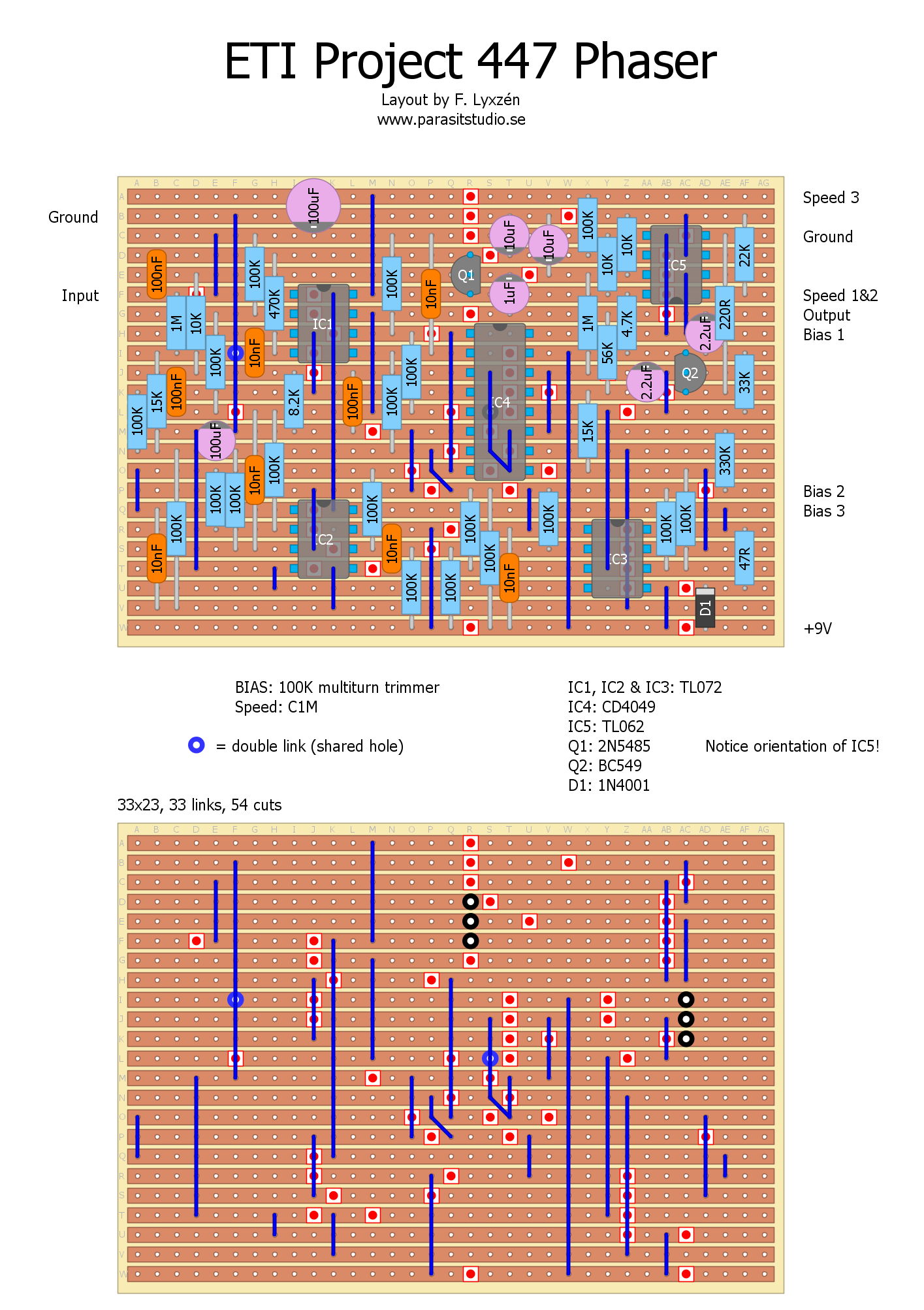 When I first built it up it was super noisy, so I modded it to reduce the voltage divider before the first phasing stage and I also reduced the makeup gain of the last transistor. Now it's totally usable, however a drawback of the mod is that there can be some minor distortion if you are using hot humbuckers.
It's important to set the Bias trimmer just right. It has a small area where phasing occurs and it controls the waveshape of the sweep aswell. There are a couple of other things to notice. When I drew up the layout I mistook the Bias pot for a Depth pot.. I don't wanna add the trimmer to the board, because it would mean even more cuts, links and possible a larger board (now it fits perfectly in a 1590BB). so, you will have to put the Bias trimmer on a separate small piece of vero. The last thing is that it needs a 100K resistor from the output to ground, otherwise it will pop when switching to bypass (the original didn't have true bypass). It is easily soldered directly to the 3PDT switch.
7 Comments
agung setiadi zainal abidin
10/12/2014 04:39:32 pm
Hy Mr fredirik
agung setiafi zainal abidin ashole
10/12/2014 04:42:32 pm
my soldering , jumper position, and component placement is OK 10/12/2014 09:39:50 pm
Hi Agung. I'm sorry to head that you have trouble with you build.
agung setiadi zainal abidin
10/22/2014 07:39:01 pm
Hy 10/22/2014 08:36:47 pm
I'm glad you got it working! :) Strange that other opamps didn't work. I agree that the speed is too slow. You could try to reduce to 100K resistor that goes to Speed 3 to increase the speed. Try a 10K resistor insted, it should make a big difference. Cheers / Fredrik 3/10/2015 09:25:55 am
Hi-fi, what do you mean by this quite? I didn't design this phaser, so i'm just stating that the original is this way and the vero follows the schematic except for the mod to reduce distortion as mentioned. As I suggested in a earlier comment, it would be possible to mod the LFO by reducing the 100K resistor to increase the rate. :) My own parasite phaser sounds better imho, so I recommend building that one insted. There's a vero layout for it in the original designs section. Cheers / Fredrik Leave a Reply. |
vero layoutsAll the layouts are Verified unless noted. Archives
February 2018
Categories
All
|
 RSS Feed