|
EDIT 2014-10-20 I added a soundclip. Here is a PT2399 based chorus by Distorque. I was a bit hesitant about this one because of the PT2399, but it sounds great. Very lush and deep. :) Original thread here. 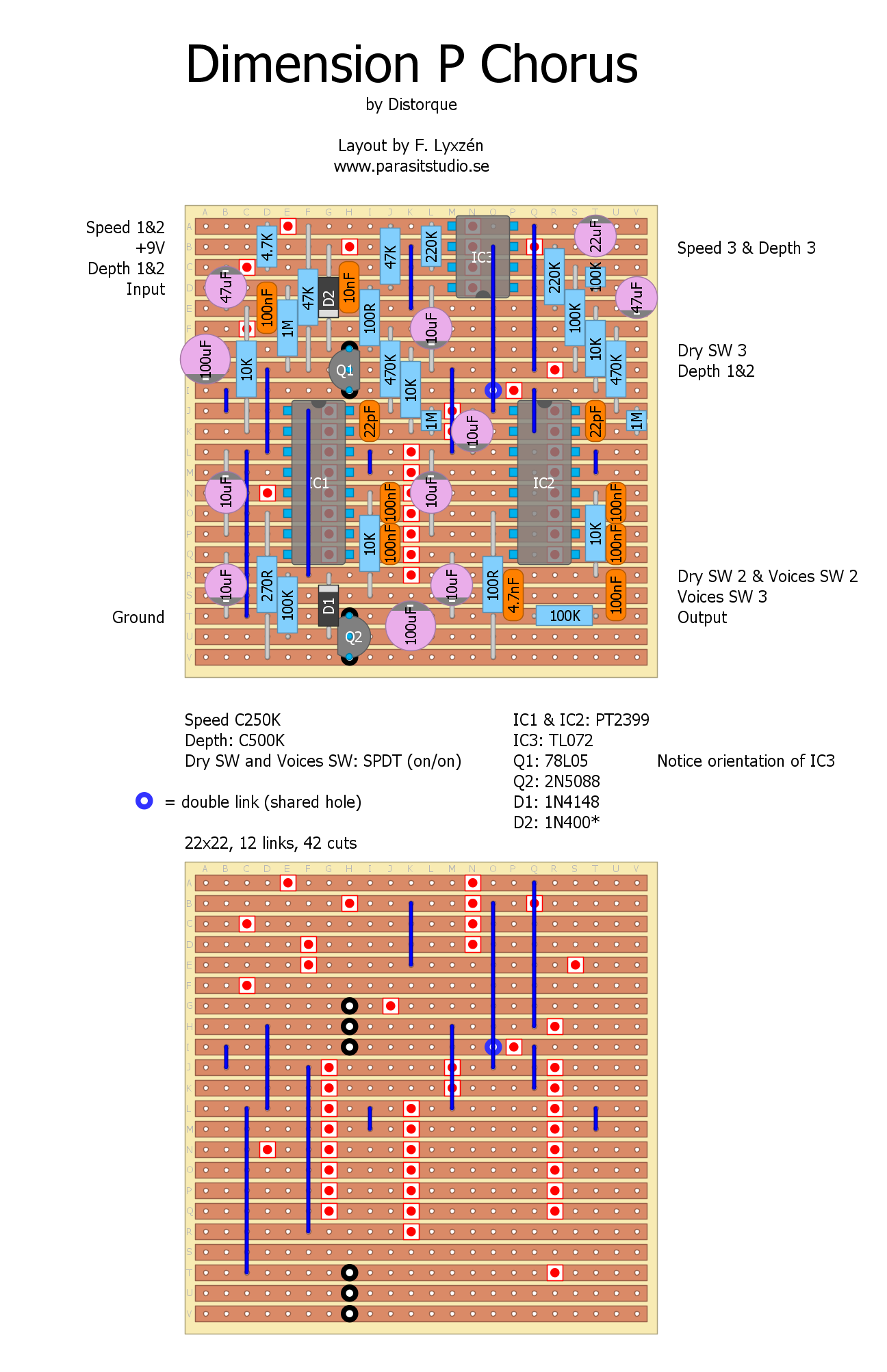 If anyone wonders, depth lugs 1&2 are supposed to connect from two point on the board. It's not a typo :)
32 Comments
agung setiadi zainal abidin ashole he
10/13/2014 02:43:51 pm
Hy mr fredrik 10/13/2014 07:45:17 pm
Hallo
Mictester
4/7/2015 09:18:16 pm
As shown, there are several problems with this circuit: 4/10/2015 08:20:52 pm
Thanks for bringing these issues to my attention. :)
Phil Gemmell
2/25/2019 04:47:37 pm
Which pin is the modulation oscillator? Where should 4.5v go?
Phil Gemmell
3/20/2019 04:11:37 pm
Is "hitting the rail" likely to cause oscillation? I'm using separate 78L05s but getting harsh squealing after about 20 seconds of running. Turning off and back on doesn't stop it. I'm going to use an lm317 at 4.5v tonight and see how it performs.
Philip Gemmell
3/23/2019 02:50:03 am
Mictester has excellent advice on this build. I have built one and it runs perfectly and quietly. Using a 78L05 for the 1st PT2399 and an LM317 network producing 4.5v for the 2nd one. The LM317 does get warm so don't bury it in anything.
roseblood11
8/18/2015 06:46:47 pm
This circuit sounds so good that it's really worth to improve it. I built it, but never boxed it up, because I couldn't get rid of the noise. Have you ever tried to include mictesters suggestions? If you could solve the problems, this could even work as a commercial pedal (or at least sell a lot of pcb's...) 8/20/2015 04:15:07 am
I agree that this would be worth improving using those suggestions to start off with. A dual layer PCB layout with a proper groundplane would probably take care of most of the noise issues alone. But I would feel bad selling PCB's and making money out of someone else's work, even if they gave me their permission. For now I'll stick with just selling PCB's of my own designs.
roseblood11
12/4/2015 02:29:57 pm
This was such a great project, but there never was a "final" version...
TazFr
5/6/2018 06:14:54 am
Very very great work. Convinced it could be the best DIY lusch chorus (in stereo!) Hope one savior could prototype PCB including best of both world + all improvements... I would for sure be the first one to buy it !
Built another one of these and had a lot of oscillation and noise. I followed Mictester's first suggestion and supplied each PT2399 with it's own 78L05 and that alone quieted most of the oscillation. Now I really have to turn my amp unrealistically loud to hear any LFO ticking.
tazidore
10/17/2018 02:23:44 am
Thanks Doxasound, very interesting post. I'll follow your suggestions.
darpi
1/14/2019 02:43:37 am
Hvat with input buffer and poor opamp as NJM2904L, LM358 in LFO 1/14/2019 02:51:29 am
Sorry, I don't understand your question. If you have any question regarding the design, please ask in the freestompboxes thread. I did not design this effect, I just made the vero layout. Cheers / Fredrik
Phil Gemmell
3/21/2019 04:39:56 pm
Ok. Built and complete. Instead of a 2nd 78L05 I used an LM317 with R1 at 150r and R2 at 390r. This produced 4.5v to power the 2nd PT2399. No ticking, no oscillation, no hissing, just chorus.
timothy
2/27/2020 05:04:39 pm
right now since I don't understand the switches I just have 2 of the wires that are supposed to go to the spdt switches connected and I get a nice vibrato.
Brit
8/22/2020 05:08:09 pm
How did you go about this on vero? Having a hard time adding the lm317 and both r1 and r2. Thank you
timothy
2/26/2020 05:40:25 pm
I have the same exact problem. still trying to figure it out. ill let you know if I do
Phil Gemmell
2/27/2020 12:12:48 am
Hi Tim, depth 1& 2 are linked. Easy to just link it at the pot and run a single wire to the board.
timothy
2/27/2020 04:49:02 pm
thanks for the response. I don't quite understand how to wire the switches. theres only 4 wires total for 2 spdt switches? how does one wire these spdt switches?
Phil Gemmell
2/27/2020 04:58:44 pm
There is a standard numering of switch terminals. Google spdt on on switch pinout and it should explain the numbers.
jyt
2/6/2020 06:22:51 pm
this must be the same one not?
djyt
2/6/2020 06:49:31 pm
Sorry did see the link on the first post, same one. But does anyone have a revise schematic of this
Dylan A Stratman
4/1/2020 10:18:47 pm
Hey there. I just finished this the other day and I am having an issue with the voices switch, where as I’m only getting any chorus/vibrato sounds with it connecting v2-v3. Any ideas?
mictester
7/13/2021 10:10:59 am
I've just noticed - on the Vero layout above, the TL072 pin 8 is not connected to the supply! You've missed a link,
Fredrik Lyxzen
7/15/2021 05:35:10 am
+9V is connected through the 100R resistor
Ted Schoenling
1/21/2022 11:59:58 am
Okay. I built this the way it was laid out and while it worked, there was the clicking and swooshing noise.
Ted Schoenling
1/22/2022 08:32:34 am
Didn't like the treble boost in front.. so I used the baxandal layout on this site and THAT did the trick.....
Derek
2/21/2022 01:28:25 pm
Why is there a cut on D-N? The fifth pin on IC1 doesn't appear to go anywhere. I'm guessing part of the original designer's unfinished work? Leave a Reply. |
vero layoutsAll the layouts are Verified unless noted. Archives
February 2018
Categories
All
|
 RSS Feed