|
A very cool sounding ring modulator by Carlin. Have a look at my completed build here. I put a 4.7nF cap between vol lug 1 and 3 (ringmod output - ground) on my build to tame some of the treble a bit. UPDATE: Now updated with a oscillator daughterboard to make it much more useful. :) On its own the Carlin Ringmod sounds kinda like a starved octave fuzz. To achieve the typical ringmod effect you have to connect an external tone-generator. Sadly not without the classic ringmod problem - carrier bleedthough (alot in this case). But my daughterboard takes care of that issue.  My idea was to put the tone generator in the box with a in/out switch insted of having two inputs like the original. I also wanted the signal to gate when not playing. This is what I came up with and it's working great.  it's a VCO (voltage controlled oscillator) controlled by a VCA (voltage controlled amplifier), which means that the VCA is triggered by the guitar signal and turns off the VCO when not playing - no more carrier bleedthough. :) The idea came from the Penfold Fuzz Unit circuit thanks to Moosapotamus video and the oscillator is taken from the LM13700 datasheet, modified for single supply and useful freqency range. 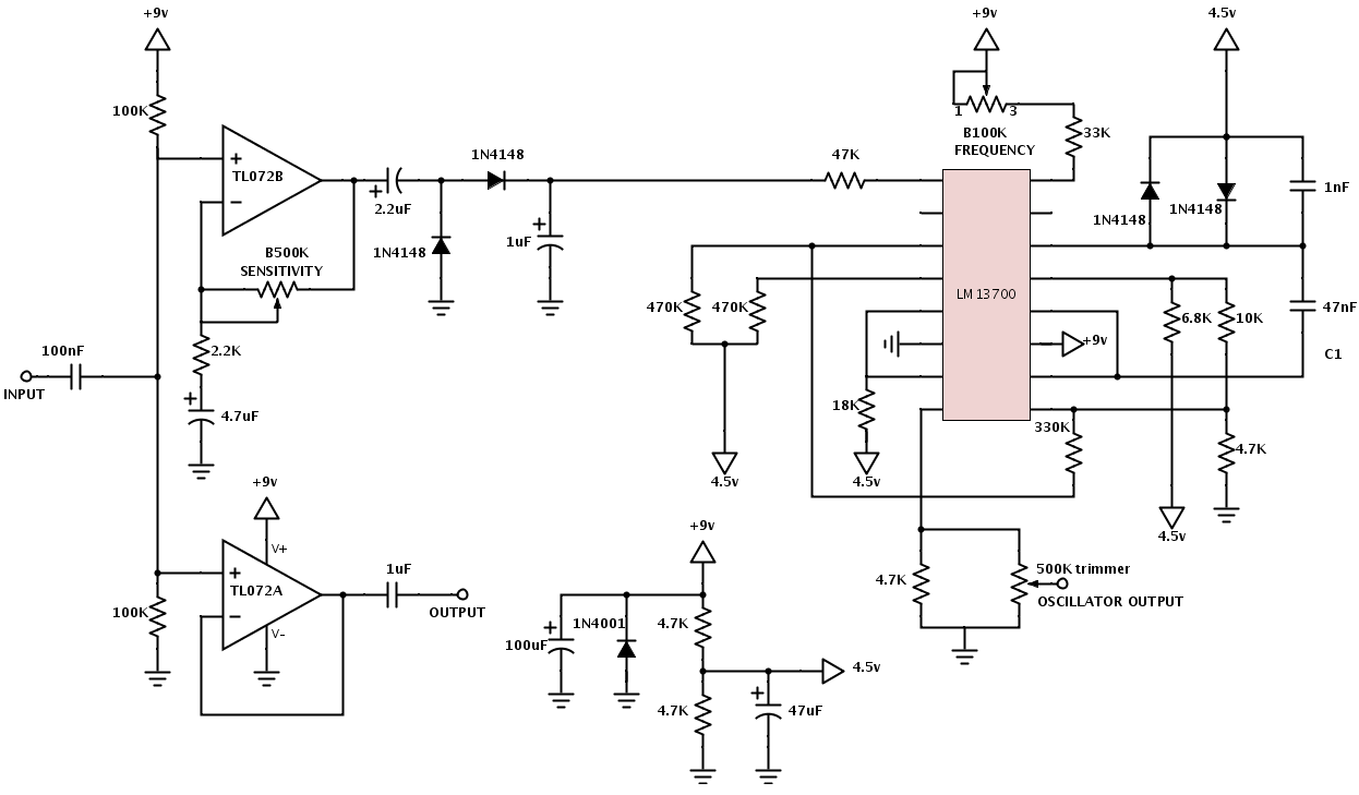 Schematic
24 Comments
Jay
7/29/2014 09:38:39 pm
Liking the sound of your mod to the original. Am I correct in thinking I need to use both strip board layouts above, or is your Ring Mod Oscillator layout self contained? Thanks 7/30/2014 07:24:44 am
Hi there Jay, I'm glad you like it. :) Yes, you are right. Both layouts are needed. I guess I should have clarified that. The input goes to the second layout - the oscillator board ("ringmod oscillator") and then to the first layout - the ringmod board ("carlin ringmod") though a DPDT switch. Just follow the DPDT switch wiring shown in the second layout. Cheers / Fredrik
Jay
7/30/2014 09:38:40 pm
Ah thanks, I see now & it's pretty obvious. I'm going to order the Op Amps and get to work on this. Hopefully it will work ok with a line level input (I intend sticking a drum machine through it)
Jay again
7/30/2014 10:39:52 pm
Actually, just to confirm, on you your Ringmod Oscillator layout, the 500k is a trimpot yeah? Sorry, but I haven't built very many of these. Thanks again :) 7/31/2014 12:20:53 am
Yes, it's a trimmer (a 6mm pitch version) :) One more think that I forgot to write on the layout. Make sure you don't miss the double links (shared holes) on the oscillator board, pads H-7 and L-7. Good luck, and let me know how it turns out :)
Jay
7/31/2014 03:32:56 am
Thanks for pointing out the double links. 8/1/2014 09:59:23 am
Ok cool. You take it you want to have two inputs just like the original + the oscillator? It might be a bit tricky, because when the oscillator is disengaged both the A and B input needs to be connected together to achieve the octave up mode and the "switch 1" on the oscillator board needs to be grounded to keep the oscillator from bleeding through. So I think a switched mono jack (as the original has) would not suffice, but you could always add another switch that would toggle between the build in oscillator and a second input jack. Let me think for a while on how you would wire that up and I'll post and drawing. :)
Jay
8/1/2014 11:51:17 pm
I'd really appreciate that. Thank you so much :) 8/22/2014 12:20:58 am
Hi and sorry for the late reply. I've been out touring.
Theo
8/2/2015 04:44:03 am
Hi ! Really nice sounding module ! I almost finished mine, but im totally lost with the wiring. I tried again and again but i have some issues with the DPDT and output wiring. Could you draw the jack connections please ? It would be very helpful ! 8/4/2015 02:28:57 am
Hi Théo, 2/7/2016 05:52:36 am
Hi Aisha,
Mitchell Finck
9/20/2018 07:26:35 am
Do you have a schematic layout for the ring modulator board? I can probably RE it from the strip board layout, but I'm also lazy. 9/27/2018 06:46:33 am
There's a link to build documents with the schematics on the site at: https://moodysounds.com/produkt/carlin-ringmodulator-v2/
Alex
2/24/2020 01:22:51 pm
Hi Fredrik, this is a great project. I have read all post and comments to understand the construction, but the link to build document and the link to two inputs switch are not working. Can you restore these links?
Ranko
11/4/2020 03:58:23 am
Is there a schematic for this somewhere? 11/4/2020 05:59:31 am
Moody Sounds sells a kit/pcb for it. You should find a schematic in their build document at their site.
Ranko
11/4/2020 07:34:21 am
Unfortunately, there is only User Manual on that site, not a build document. :( 11/5/2020 02:27:51 am
The schematic is on the second page of the manual PDF... :)
Ranko
11/5/2020 03:10:49 am
I can find only this file on their site: carlin-ring-eng-1c.pdf. It doesn't contain the schematic. Could you please provide me a link to the file you mention, I don't speak Swedish, so it's obvious I can't find it :( 11/5/2020 03:11:50 am
https://moodysounds.com/wp-content/uploads/2017/01/carlinringv2engc.pdf
Ranko
11/5/2020 04:11:26 am
Great, thanks! I'm really interested how does this thing works.
Luca
4/10/2021 10:06:17 am
Dear Fredrik thanks for your work! Leave a Reply. |
vero layoutsAll the layouts are Verified unless noted. Archives
February 2018
Categories
All
|
 RSS Feed