PARASIT STUDIO
  • DIY GUITAR EFFECTS
    • Original Effects
    • Building blog
    • DIY Gallery
    • Stripboard layouts
    • Articles
  • SHOP
  • BUILD DOCS
  • ABOUT

CMOS workshop part 3 - octave down

8/24/2015

23 Comments

 
Picture
6. Octave down, Flip Flops and Latches
Lets have a look at a few different ways to create octave down using CMOS chips.

In all of the examples below something called a flip flop latch will do the frequency dividing. Sometimes it's just embedded into chips with other functions. The flip flop/latch is one of the fundamental logic building blocks. It's used to store data and is how RAM memory in our computers works. One flip flop can store 1 bit of data, which means that it can hold a high or low state until we tell it otherwise. This can be very useful, for example when we want to use a momentary switch to turn something on or off until we press it again. Flip flops can also be used as oscillators, counters and much more.

But now let's focus on frequency dividing. What it does, to put it as simple as possible: Each time the clock (our input signal) goes high, the output changes state. Since the output only changes on the positive transitions and holds that state on the negative transitions we get exactly half the frequency at the output, like this:
Picture
Picture
Example of a basic S-R flip flop using NAND gates
Picture
Example of a flip flop latch
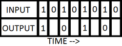
If you want to learn more about the logic math behind the flip flop, I recommend this video:
https://www.youtube.com/watch?v=PCT76PsDr6g

Pre-filtering
Making a octave down circuit with CMOS is easy since we are now working with 1's and 0's. Getting good tracking is harder, but there are a few simple measures we can take to get acceptable tracking. The first thing to keep in mind is that we can improve tracking significantly by using the neck pickup of the guitar and the treble rolled off. But we also need to add a lowpass filter after our schmitt trigger since it adds alot of high frequency content. There are many different lowpass filters we can use, varying in complexity, but for this article we'll use a simple passive RC filter.
Picture
RC lowpass filter
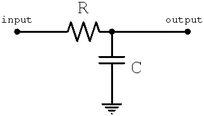
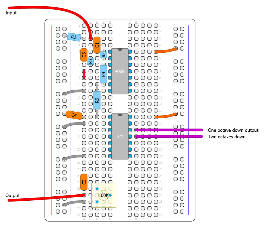
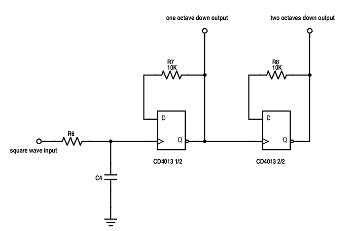
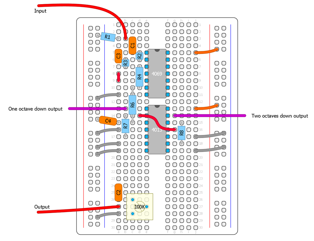
Here is a sound example of octave down with: 1. Bridge pickup, no filter 2. Bridge pickup with RC filter 3. Neck pickup with RC filter.

Let's get the breadboard ready!
We'll start out with the circuit we made in part two, then add the new section before the output capacitor. To keep it simple, the schematics will not show the "cmos'ifier" part or the output part. Lets add the RC filter first (R6/C4). 10K and 22nF-100nF is a good starting point. Then we'll add the octave down part.

No decoupling capacitor after the schmitt trigger is needed. CMOS chips are make to interface with each other directly so decoupling caps are rarley needed, except for linear amplifiers, filters or special schmitt trigger operations. It's very forgiving this way.

1. Dual D-Flip Flop (CD4013)
This chips is used in the MXR Blue Box, MadBean Lowrider, The Rocktave and many others.

This chip has two D-flip flops. The D prefix means that it changes output state on positive transitions only, exactly what we need. For two octaves down, we'll just put both flip flops of the chip in series so that the second flip flop will divide the output of the first flip flop.

  • Input goes to Clock
  • The NOT Q output (Q with a line) goes back to the data input (D) via a 10K resistor
  • Set and Reset goes to ground
  • Q or NOT Q goes to output. NOT Q is the inverted output
  • VCC to V+ and VSS to ground
Picture
CD4013 pinout

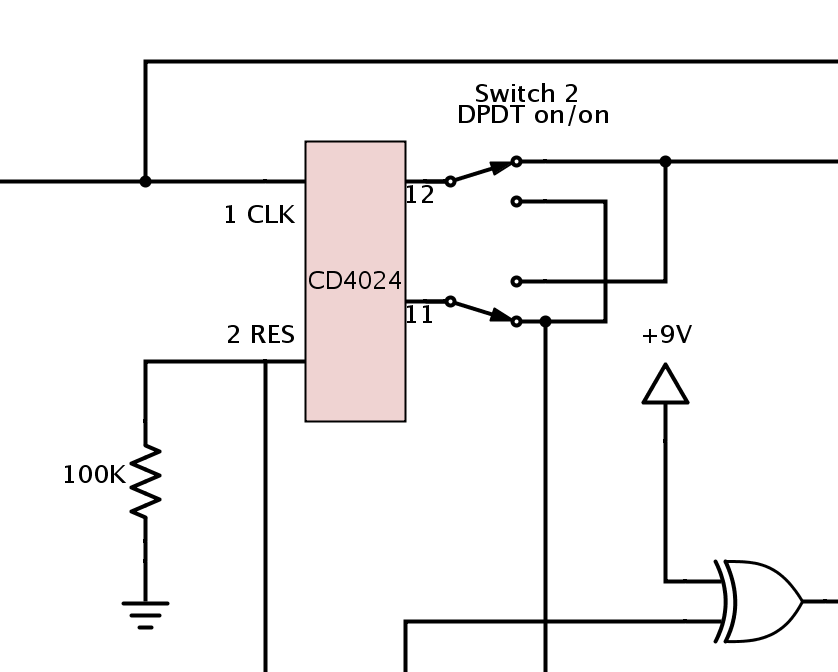
Output controls
You can use pots/trimmers as variable resistors or voltage dividers to have control over each octave or a switch to toggle between them, a blend pot/trimmer between straight square wave and octave down ect... Experiment with the controls that you want. Here are a few examples:

2. Binary Ripple Counter (CD4024)
This chip is what I used in the Arcadiator. it's very common in DIY synth stuff and it's also used in the Slacktave (by Slacker, the designer of the Echo Base) and the Bit Commander by Earthquaker Devices. It's very simple to use and require no extra external components.

The CD4024 chip is a counter that advances one count every time the clock changes from high to low. The first output is divided by two, and the next output divides the preceding output by two and so on, up to output 7 that has the input frequency divided by 128. This means that each output is one octave lower.

  • Input goes to Ø
  • Reset goes to ground
  • Q1 is the one octave down output
  • Q2 is the two octaves down output
  • VCC to V+ and VSS to ground
Picture
CD4024 pinout
Picture
Picture
Part of the Arcadiator schematic

3. NAND Gates (CD40106, CD4093)
Let's look at how it's possible to make a D-flip flop out of NAND gates.

As you can see, it requires many gates and even one 3-input gate, which means we have to use at least two chips. But remember that I mentioned that schmitt triggers can be configured to make NAND and NOR gates?

A schmitt trigger gate can be made into a multiple input NAND or NOR gate using 1N4148 diodes and a resistor, with as many inputs as we want. This is something I picked up from Ray Wilson, he calles it "mickey mouse logic". This makes the CD40106 a very versatile chip, and using this neat trick we can make a flip flop out of a single CD40106 chip.
Picture
"mickey mouse logic"
The same mickey mouse logic can be applied to the 2-input CD4093 schmitt trigger by first connecting both inputs together (which makes a NOT gate).

A good way to test these octave down circuits on the breadboard is to connect a LFO with a LED to the input and another LED at the output. That way we can easily see if it works. I tested the NAND schematic first with a freeware program called Logic Circuit just to make sure it would work, then I breadboarded it. This is the result.
For this video I used another CD40106 for the LFO. We'll cover LFO's in a later part. (Ignore the extra parts on my breadboard and the non decoupled inputs.. I cheated alittle to make it quickly...)
Picture
NAND equivalent of a D-flip flop
Picture
CD40106 flip flop schematic
Picture
Transistors bi-stable multivibrator (equivalent to a D-flip flop) from the Colorsound Octivider schematic
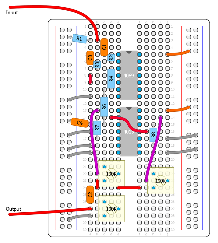
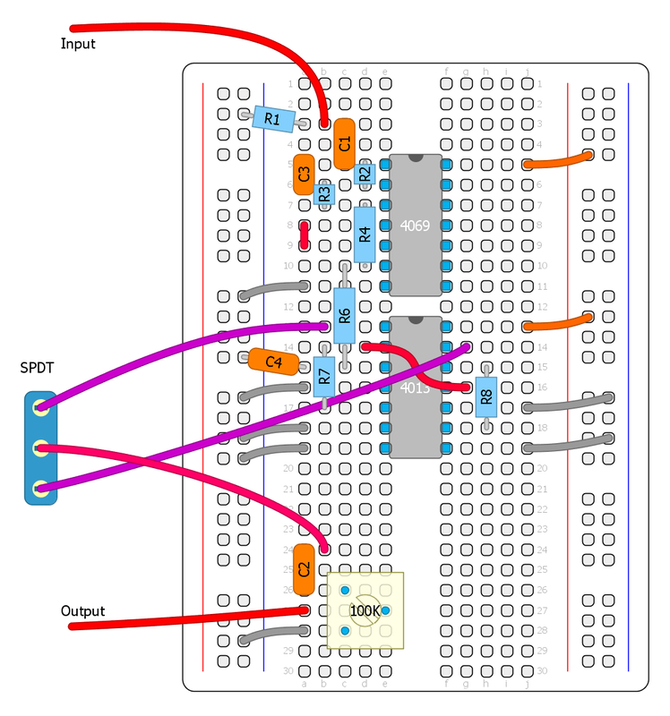
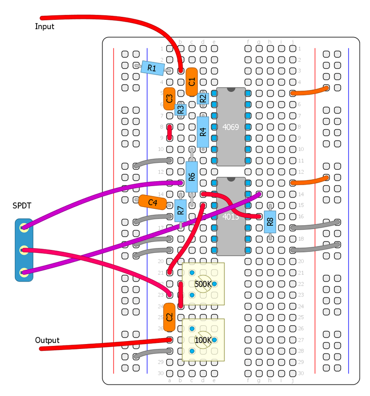
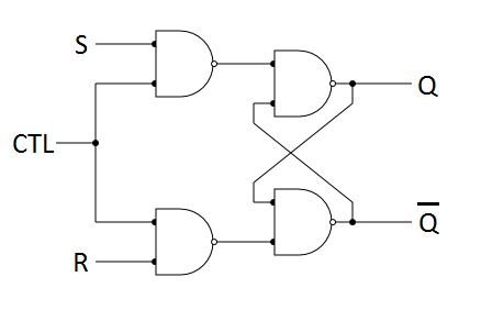
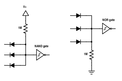
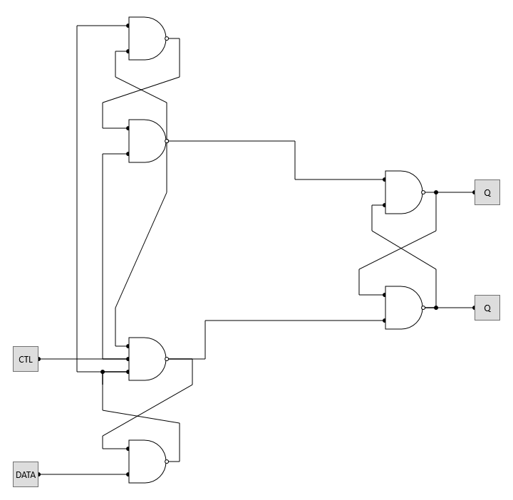
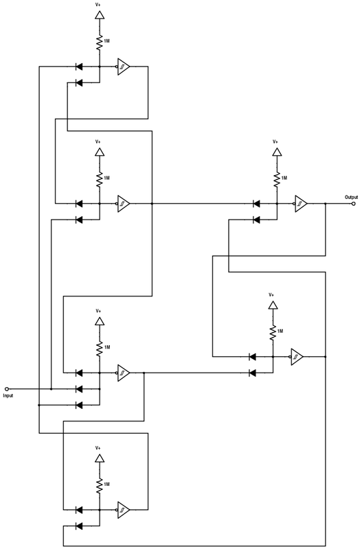
It works. :) I actually used this flip flop version for the sound example in the beginning of the post. This was very confusing to breadboard and I won't even try to make a breadboard diagram. It's not a very convenient method, unless you have a huge stash of schmitt triggers and diodes that you want to put to good use... I just wanted to show you what is possible.

Post-filtering
It can be a good idea to have a RC lowpass filter on the octave output if you want it to sound less synthy or harsh. It's common to filter out anything above around 100hz to make it blend better with a clean guitarsignal. Experiment!

I'll stop here. This post became massive and took me a whole day, and I didn't even mention octave down by using gated oscillators, phase locked loops or shift registers. Maybe more about that in a later part. But in the next part I will cover LFO's and oscillators.
We will analyze the Flawed Logic Fuzz and we will breadboard a drone synth.
23 Comments
Dayne link
8/25/2015 12:57:12 pm

I'm going to have to order up a few more CMOS chips! Thanks a lot for these articles!

Reply
hymenoptera
9/16/2015 08:33:16 pm

Great stuff, thank you so much! I was struggling with chapter 8 "Digital Electronics" in Horrowitz and Hill's The Art Of Electronics until now. It's all starting to make sense. Can't wait to breadboard the rest of these examples!

Reply
thehallofshields
9/18/2015 03:34:46 pm

Thanks so much! I've been fascinated with Octave Down circuits for like 3 years but didn't have the know-how to bread-board one until now!

The Dual Flip-Flop (4013) and the Frequency Counter (4024) sound the same to my ears! Very cool.

Reply
thehallofshields
9/18/2015 03:39:08 pm

I hope some of you guys out there are using the OC-2 ('clean') trick where you use a JFet Gate to add some dynamics back into your signal.

It sounds great even without any filtering.

Reply
Ash
3/21/2016 07:51:23 am

Can we expect a part 4 in the series anytime soon? I love this blog. I am still fairly new to breadboarding so I am not only learning how cmos chips work in effects but also breadboarding techniques since you lay everything out so well.

Reply
Fredrik Lyxzén link
3/23/2016 04:37:43 am

Hi Ash,
I will concentrate on writing the next CMOS workshop part as soon as I have a few of the current releases done (xor'cist, parasite phaser). Cheers / Fredrik

Reply
Ash
3/23/2016 03:34:00 pm

No worries my friend! Still plenty here to keep me busy.

Sergio
1/13/2017 10:46:17 am

Hallo. Great article, reading the 4024 part I get intrigued why I cant remember hearing about an octaver that reaches a 3 octaves down as it seems to be possible for it to reach. I should breadboard this. Has someone already tried? Does it barely sound? Or does it sound not very musical? Thanks a lot.

Reply
Fredrik Lyxzén link
1/14/2017 04:32:52 am

Hi Sergio,
Thank you. Yes, it's no problem making a third octave down using the 4024 chip, but IMO it's not very usable or musical. You should breadboard it and try for yourself. :)

Reply
flanagan0718 link
3/8/2017 12:59:42 pm

Hey Fredrik,
This has been super helpful so far. Thanks for showing the breadboard examples. I suck at bread boarding so this is helpful in many ways!!!

Reply
Fredrik Lyxzén link
3/8/2017 01:25:11 pm

Hi Mike,
I'm glad that you find it helpful. :)
Cheers / Fredrik

Reply
Shane
5/18/2017 09:21:42 pm

Great article, Have just been experimenting with using a CD4040 and getting some really crazy and fun results!

Reply
Fredrik Lyxzén link
5/19/2017 09:04:47 am

Hi Shane,
Thanks. I'm glad you found it useful. :)
Cheers / Fredrik

Reply
Rhuan Cardilo
2/25/2018 06:33:18 pm

Hey Man, please continue with this series! It´s fantastic... I´m working with some pedals based on CMOS chips, and this is very inspiring... thanks so much, and, if possible, continue this great job... Greetings from Brazil!

Reply
golden axe
9/29/2018 01:00:46 am

amazing series of tutorials , been doing octave down with 4040 which is a dedicated cmos divider chip , you just need the clock and then youve got yourself 10 divisions down, very cool

Reply
Fredrik Lyxzén link
9/30/2018 12:16:36 pm

Thanks, glad to hear that the tutorials are appreciated. :) Cheers / Fredrik

Reply
Jefrei link
1/29/2020 05:19:26 pm

Quisiera saber si puedo hacer un octavador, ejemplo, de dos octavador abajo. Pero quisiera usar transistores, como el shoktave down, solo que fuera más como el BOSS OC-2, que es limpio y no suena fuzz, crees poder ayudarme. Sería genial con un diagrama que indique preamp, amp, effect, mixers, buffers,etc. Desde ya muchas gracias y que Dios te bendiga

Reply
Dan
2/19/2021 10:57:16 pm

In english you piece of shit.
You must be ond of those pathetic argentinians

Reply
Albert
5/4/2020 08:50:00 am

Hello! Will you make an LFO workshop? It would be amazing

Reply
Mariano segat link
5/6/2020 07:21:10 am

Hi Fredrik.

I was digging this articles and can't understand whats the logic in the 8bitar for the octave down. From what I undestand here, the basic way is using ripple counters, or making a frequency divider out of flip flops, or making a flip flop out of nand gates, or making a flip flop out of nand gates made out of schmitt triggers and micky mouse logic.

But in the 8 bitar, after the standard *c-mosifyer* stage, we just got 2 more inverters in series. How does that work for an octave down?

Thanks for your time.

Cheers/ Mariano

Reply
Fredrik Lyxzén Parasit Studio link
5/9/2020 02:32:39 am

Hi Mariano,

The two inverters together with the transistor and the surrounding components actually forms a type of flipflop. It's normally seem in push button schematics.

Both inverters are cross connected, just like a NAND gate flipflop so that it has two stable states, R8+R9 forms a schmitt trigger, With the switch on (the transistor in this case) it will either charge or drain the capacitor (C6) depending on the current state of the gates, making the invertes change state until the next time the switch is opened.

It's hard to explain here without a long text, but if you think about the logic of the invertes and the current flow, it's actually quite simple. :) Cheers / Fredrik

Reply
Jim
6/12/2020 10:20:24 pm

I breaded boarded this circuit months ago with a CD4049 and CD4013. I think I ran a separate fuzz off the other side of the CD4049 and somehow got what I think was an 1.5 octave down....(is that a divide by 3?) which I ran underneath the straight fuzz. It was so cool. I took a picture of the breadboard, but a month later my hard drive crashed and lost it. and my child since decided to make a toy out of the breadboard.

I hate to ask, "But how did I arrive at that happy accident?"

Reply
Fredrik Lyxzen link
6/15/2020 01:35:23 pm

Hi Jim!
Sorry, I have no idea haha. Perhaps you mixed octaves together with diodes? That can result in an odd division (but the waveshape is usually not a 50/50 square). There's other ways of making divide by 3 (or any number) but usually much more complicated. Anyway, glad to hear that you had some fun breadboarding stuff from these articles (but sorry about the hard drive crash. That sucks).
Cheers / Fredrik

Reply


Leave a Reply.

  • DIY GUITAR EFFECTS
    • Original Effects
    • Building blog
    • DIY Gallery
    • Stripboard layouts
    • Articles
  • SHOP
  • BUILD DOCS
  • ABOUT