PARASIT STUDIO
  • DIY GUITAR EFFECTS
    • Original Effects
    • Building blog
    • DIY Gallery
    • Stripboard layouts
    • Articles
  • SHOP
  • BUILD DOCS
  • ABOUT

CMOS workshop part 2 - square wave fuzz

8/21/2015

29 Comments

 
Now onto the fun stuff. :)

But first, there's a couple of important things to watch for when using CMOS.

3. CMOS usage rules
  • All inputs must go somewhere. A unused gate must be disabled by connecting it to either +9V or ground, directly or with resistor. The input of a CMOS gate is very high impedance, so a floating input can randomly determine what the circuit will do, making it change state erratically, causing noise and high current draw.
  • Inputs that goes off board should have a load resistor connected (1M resistor to ground).
  • CMOS chips are sensitive to static. They have built in protection diodes, but sometimes it's not enough. It's a good idea to wear a anti-static wristband when working with CMOS.
  • CMOS chips accept a wide range of supply voltages (generally from around +3v to +15v), but it's always a good idea to double check the datasheet just to sure. There are exceptions. We will only be using chips that works well with +9 volts.
Picture
The "CMOS'ifier" square wave fuzz on the breadboard

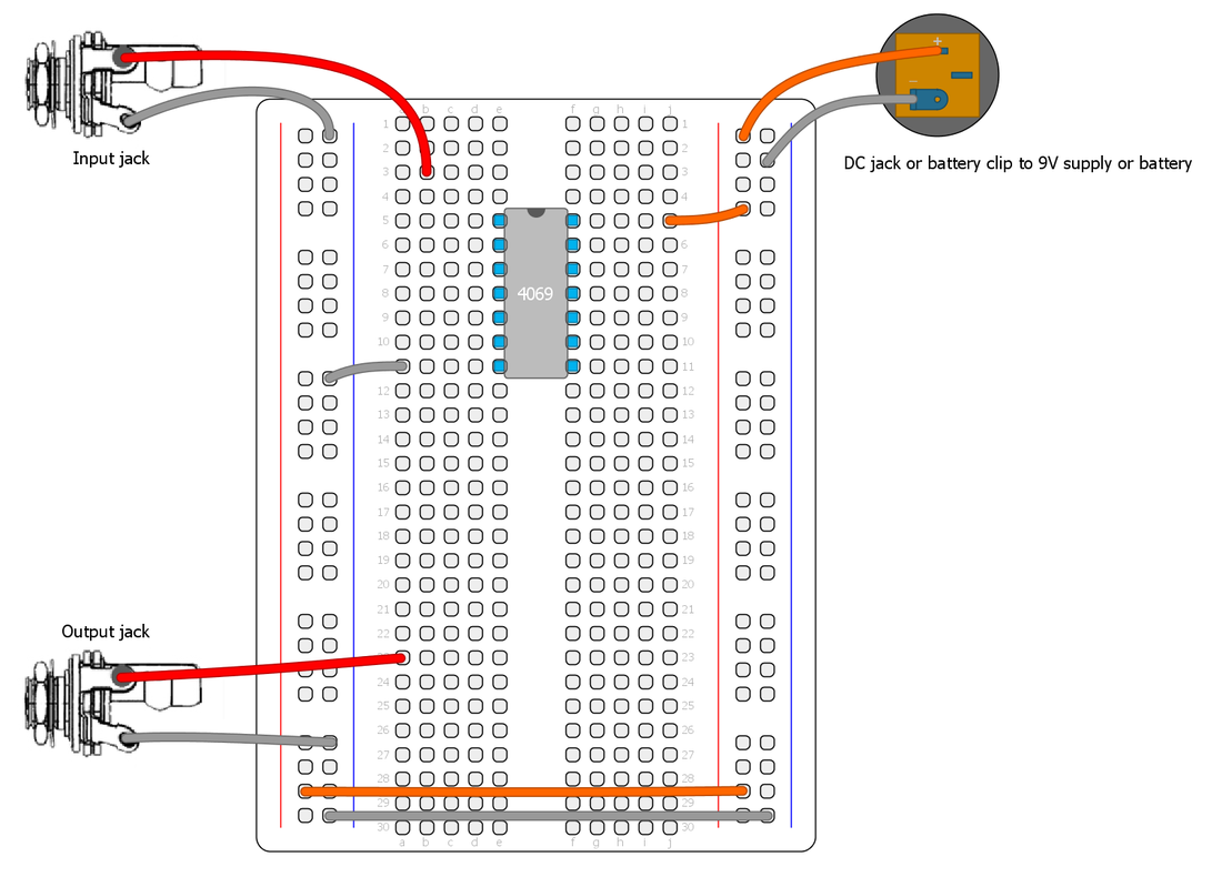
4. Pulldown/up resistors
These resistors are often needed in CMOS circuits. They are useful when we want to force a high or low output state when the input is not changing, but still leave the input able to accept a input signal. They are typically a high value from 10K - 100K and goes to ground (pulldown) or V+ (pullup) at the input of the gate. For example, if we have a gated oscillator on the input and we want  to make sure the output always goes to ground when the oscillator is off we need a pullup resistor at the input (assuming the gate is inverting). We will use a few pratical examples later on.

5. Lets breadboard the "CMOS'ifier", a simple square wave fuzz.

We will use this circuit as the front end for the guitar signal, so we can do other things later on, such as octave down. But it also makes a pretty cool fuzz on it's own.
For this we will use a CD4069 chip, simply because it has a easier pinout than the CD4049 and takes less space on the breadboard. First, lets take a look at the pinout of this chip. Lets connect input/output jacks, power and ground to the breadboard and the chip like this (these connections will not be shown later):
Picture
CD4069 pinout
Picture
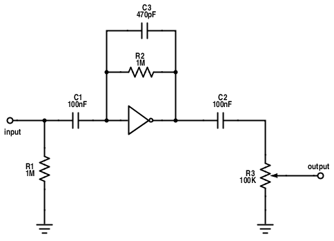
Stage 1. Preamp
Our first stage of our circuit will be boosting the guitar signal into logic levels. This is a gainstage similar to many CMOS based distortions, such as the classic Tube Sound Fuzz by Craig Anderton. This is one of the exceptions to the digital logic and can only be done with the CD4069/CD4049. It gives a very pleasing distortion, but has the drawback of being rather noisy.
We will configure one stage of the inverter by adding negative feedback, using a resistor from the input to the output of the inverter and decoupling capacitors.

  • R1: Load resistor
  • R2: Sets the gain of the amplifier. Try a 1M trimmer/pot here insted for controlling the gain.
  • C1 and C2: Decoupling capacitors. This is always needed at the input and output of a circuit, but it's also nessecery for the input of a linear amplifier to work properly.
  • R3: voltage divider trimmer to control the output volume.
  • C3: optional lowpass filter cap. Can be anything from 100pf to 47nF. How much treble it cuts depends on the value of R2 aswell. Experiment with different values!
Picture
Stage 1: linear amplifier gainstage
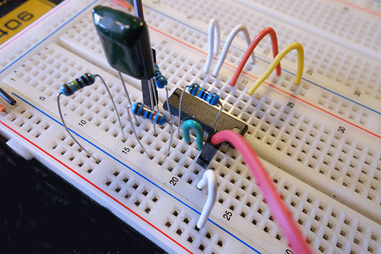
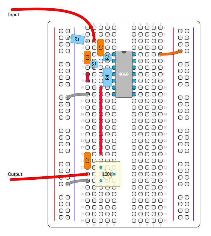
Lets put it up on the breadboard. Notice the green wires in the first image that are used to disable all the unused inputs. This will not be shown later, but it's a good pratice to always disable any unused input. The second image shows the same circuit with a trimmer for gain control. Put several gainstages in series for a sweet sounding distortion. I usually have two gainstages in my designs when I have one extra inverter left over.
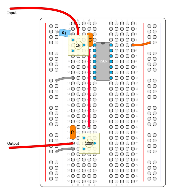
We can use any circuit to boost the signal into logic levels, transistor-based or op amp, but the advantage with this method is that we're only used 1/6 of one chip. So the rest of the inverters can still be used for other things, oscillators, LFO, filters ect. and this will save us some space. Another easy way is to use a LM386 amplifier chip and boost the signals into a squarewave (common in many Tim Escobedo designs), or a op amp comparator.


Stage 2. Schmitt Trigger
This stage completes the "CMOS'ifier". It will turn the signal into a square wave, making it compatible with other CMOS chips. This part is inserted before the output capacitor. R3 and R4 sets the upper and lower thresholds for the schmitt trigger. It's best to leave R4 at 1M and experiment with the lower threshold resistor R3. Higher values will make it more gated, but low values can result in oscillation. Here we need to find the sweetspot that depends on how strong input signal we are getting. Increasing the value of C3 (1nF - 22nF) can also help against oscillation, noise and misstriggering. Very low output pickups may sound too gated, in that case use two preamp stages in series before the schmitt trigger to increase the sustain.

If we have a schmitt trigger chip (CD40106 or CD4093) in our design we can just use one gate of that chip insted directly after our preamp stage. In that case a pulldown resistor (100K to ground should always be used at the first schmitt trigger input.


As you may notice, a square wave is pretty much immune to any filtering that comes before it and will sound the same no matter what kind of circuit we use to create it.

In the next part, we'll have a look at doing something a bit more advanced - several few ways to achieve octave down!

I hope this series is interesting. I'm trying to keep it as basic as possible, but it will become more advanced in later parts. Please let me know what you think and if there is anything I can improve. Thanks!
Picture
The complete "CMOS'ifier" fuzz
Picture
The complete circuit on the breadboard

Next part: CMOS workshop part 3
29 Comments
thehallofshields
8/22/2015 07:11:54 am

I'm trying this with a 4049 and second stage is incredibly gated. It takes an additional gain of 10 from a pedal to get a steady signal through.

I've got the pinout right, stage 1 sounds great (just like the Anderton TSF). I've tried a bunch of different values for R4. All unused Inputs are tied to V+.

Any suggestions?

Reply
Fredrik Lyxzén link
8/22/2015 06:34:12 pm

Hi,
Fun to see that someone is actually reading this and playing around with it.

Strange, it's should not be super gated, unless you are using a guitar with a very low output maybe? You can put two gainstages in series if needed. I've never used a schmitt trigger with a cd4049 so that could be the issue. They should be interchangable, but you never know.. Some functions (like integrators) works better with the UBE (unbuffered) of the chip, but that should not matter here either.. Just thinking out loud here. Maybe you should try a CD4069 and see if it makes a difference?

I've updated the post and added a mention about pickups and op amps comparators.

/ Fredrik

Reply
thehallofshields
8/26/2015 06:30:48 am

I'm still having issues using the 4049 as a Schmitt Trigger.

To get more than just my signal peaks through, I had to add 100k series resistance to V+. -Extreme, I know!

Reply
Fredrik Lyxzén link
8/27/2015 08:50:00 am

I just realized a type in my post. R4 should be the fixed 1M value and you should play around with R3. Sorry about that! There isn't even a R5 which I mention in the same sentence.. :P Anyway, try R3: 10-47 K and R4: 1M. It should work alot better!
I have updated the post.

Reply
thehallofshields
9/18/2015 03:21:09 pm

I switched over from a 4049 to a 4069 then realized:

Oops! I mistook a 10M for a 1M Resistor. Green and Blue are so hard to tell apart!

Marek
8/24/2015 01:46:35 am

Is there a CMOS like the CD4049UBE that isn't that noisy?
Or is there any way to avoid it at full gain?

Reply
Fredrik Lyxzén link
8/24/2015 06:36:10 am

Hi Marek,
No, there is nothing else like the CD4049 that is less noisy. I wish there was. I love my Red Llama, but it has a ocean on noise...
cheers / Fredrik

Reply
Marek
8/24/2015 07:00:45 pm

Would it be less noisy if i would make the inverters "by hand" using a n-channel transistor and a p-channel transistor? could i get there somehow?

thehallofshields
8/25/2015 05:23:46 am

Take a look at PureTube's 'SansValve'.

http://smg.photobucket.com/user/latronax/media/sansvalve2138.jpg.html

http://www.diystompboxes.com/smfforum/index.php?topic=59383

I'd give it a try, but I don't have any P-Channel MOSFets on-hand.

Marek
8/25/2015 06:23:04 pm

Thanks man, this is pretty much what i looked for ^^

Fredrik Lyxzén link
8/27/2015 08:57:09 am

That's cool! I think I'll draw up a vero layout for the sansvalve, or experiment with a couple of them in series with a CD4007. :)

thehallofshields
9/18/2015 03:31:47 pm

I don't find the 4049 to be that noisy when you turn down the gain by lowering the Feedback Resistors.

Try cascading stages of 100k - 250k and let an Opamp do most of the Amplification. It cleans-up without the noise waterfall.

Fredrik Lyxzén link
8/25/2015 03:50:13 am

I'm afraid that I don't know how that would be possible, but it's an interesting idea

Reply
Synsound
8/24/2015 02:26:18 pm

I'm excited to follow these lessons. I want to wait to read part one so I don't get ahead of myself. From the little I have read it seems well written for someone with little technical background, like me, to follow and comprehend. Thanks for the circuits and now the knowledge. Keep up the good work!

Reply
Fredrik Lyxzén link
8/25/2015 03:34:09 am

Glad you appreciate my effort. :)

Reply
Charles
8/25/2015 02:58:20 pm

Yeah man this rules, thanks Fredrik.

thehallofshields
9/7/2015 02:29:19 pm

Could you explain the Schmitt Trigger arrangement?
Why do the Inverters share the Negative Feedback Resistor?
Is the goal just maximum gain, or is there another principle at work?

Reply
Fredrik Lyxzén link
9/15/2015 02:25:43 pm

Sorry, I missed your comment. There is another principle at work here, not just maximum gain. The resistors sets the threshold for triggering action depending on the input voltage. The linear amplifier configuration is not at work at all here. Sorry, I wish I could explain it better but that would require a looong reply. :)

Reply
thehallofshields
9/18/2015 03:26:42 pm

Got it. I wish I could better understand how the Supply Voltage, Input Resistor and Feedback Resistor all contribute to the Gain, Gating Threshold and Output Impedance.

How different are the principles of these NOT Gates to Inverting Op-Amps?

Marek
10/19/2015 04:03:58 am

Hi, me again.
I have a question regarding switching gates in/out.
I am trying to make an overdrive with two modes and want to switch in an addidtional gate.
I am using two gates and bypass one for light overdrive and switch the first one back in for heavier overdrive/distortion.
Now to my problem: only the 3 gate configuration works and i only have a load resistor on the first one(that one thats needed for the heavier tone). Do i need a load resistor on the second gate too if it is the first one that the input is going to?
Thx in advance.

Reply
thehallofshields
3/19/2016 12:38:26 pm

The Schmitt Trigger will only switch after the Zero-Crossing + 1/3 of the Supply-Voltage right? Does this eliminate the need for low-pass filtering?

Why do other Fundemental Detectors use op-amp comparators when the CMOS Schmitt Trigger has Gating and Zero-Crossing detection without any extra work?

Reply
Fredrik Lyxzén link
3/23/2016 04:43:29 am

Yes, you are right. But it doesn't eliminate the need for low-pass filtering.

The cmos schmitt trigger has fixed thresholds that can't be changed, so often an op amp comparator is a better choice since it can be configured for both threshold and hysteresis levels.

Reply
pango
7/12/2017 10:00:53 am

Hi Fredrik, thanks for posting this!

The resistors you refer to in the explanation, are they they numbered the same as in the schematic or the breadboard layout? (I notice they are different).

Reply
Jakob
8/6/2017 02:43:37 am

Does your CD4069 get really hot? or is it just me?

Reply
Andy
11/16/2018 01:44:34 am

Is the resistor labelling here wrong? :

"Stage 2. Schmitt Trigger
R3 and R4 sets the upper and lower thresholds for the schmitt trigger. It's best to leave R4 at 1M and experiment with the lower threshold resistor R3. "

The schematic seems to indicate that you meant to leave R5 at 1M, not R4, and experiment with the value of R4.

I'm now not clear which resistors you meant that set the upper and lower thresholds.

Did you change the schematic but forget to update the text to match?

Reply
Fredrik Lyxzén link
11/16/2018 09:30:44 am

Hi Andy,

Yes, the R3 on the schematic is actually R4 on the breadboard image, and R4 on the schematic is R5 on the breadboard image. Sorry about the confusion.

Some self critique/additional info: the text should be clarified to say that R4 (the input resistor) sets the hysteresis level (both the upper and lower threshold in relation to R5 (the positive feedback resistor).

You can think of it like this: R4/R5 basically forms a voltage divider. When the schmitt trigger output goes low, R5 is effectively connected to ground so the input signal gets offset/pulled closer to ground, so it has to rise a bit further to cross the half supply voltage threshold (the chip threshold always stays the same) and when the schmitt trigger output goes high, R5 is connected to your positive supply voltage so the signal is pulled closer to V+ and needs to swing lower to cross the threshold. Thus creating hysteresis by shifting the input signal offset up and down. I hope that makes sense.

I'll do an overhaul of these articles soon. Thank you for your interest. :)

Reply
Andy
11/19/2018 02:44:36 am

Thanks. I like the idea that the Schmitt trigger can be made adjustable.

I guess you can get the same sort of effect by varying the gain or signal level of the stage before it, but there might be some advantage, like maybe noise immunity.

Feri
11/3/2019 05:39:27 am

Hey Friedrik!

I've built this fuzz, with a 4049 on 12V. At first it was incredibly gated, bc im using a low output bass. But when i put a 22nf cap between the input and ground, it became a different beast! Now it works as its supposed to. I guess it is bc of the sorta "fixed tone pot". Anyways, great article, i hope you will continue this series! Thanks, and greetings from Hungary ;)

Reply
Macie link
12/6/2020 04:46:23 pm

Your the bbest

Reply


Leave a Reply.

  • DIY GUITAR EFFECTS
    • Original Effects
    • Building blog
    • DIY Gallery
    • Stripboard layouts
    • Articles
  • SHOP
  • BUILD DOCS
  • ABOUT