PARASIT STUDIO
  • DIY GUITAR EFFECTS
    • Original Effects
    • Building blog
    • DIY Gallery
    • Stripboard layouts
    • Articles
  • SHOP
  • BUILD DOCS
  • ABOUT

CMOS workshop part 1 - basics

8/19/2015

5 Comments

 
Many of my designs are based around CMOS chips and a few people has asked me if I know any good resource for stompbox designs based on CMOS. I don't really...

So I thought it might be fun to share alittle of my knowledge of the CMOS basics and hopefully you will learn something and will be able to experiment with your own CMOS based circuits.

We will use the breadboard later, but first, lets start with the basics (the boring stuff...)
I won't go into detail on how they work on the insides. For that I really recommend reading the book: The CMOS Cookbook. It's been a huge help and inspiration for me.

1. CMOS LOGIC
The first thing one must understand is that CMOS works with digital logic:
They put out 1 or 0 at their output, depending on the 1's and 0's on their input(s).
These two states are also often called "high or low", "true or false" or "on or off" ect.

I think it's easiest to think of these two states as either V+ or Ground

1 = V+ (high)
0 = Ground (low)

There are exceptions that doesn't follow this logic.

This means that no matter which kind of waveshape we put into a CMOS logic chip, the output will always be a squarewave. There is no in-between, no dynamic range, just 1's and 0's. The output logic changes at about halfway up the power-supply voltage, so to be able to use a CMOS chip with a guitarsignal, the signal needs to be boosted into logic levels, then preferably made into a square wave: digitalizing the signal (in a crude way). This is the reason you don't see a gain control on many of my designs and why it often sounds totally fuzzy. A square wave is as distorted as it can get. This is also the reason why the output of a CMOS based guitar effect have a gated sound with a decay that dies abruptly (as the input signal falls below the schmitt trigger threshold).


More about schmitt triggers later.
Picture
The Arcadiator uses 3 CMOS chips
Picture
Don Lancaster's CMOS Cookbook

Here's a short video of my oscilloscope that displays a guitar signal that is boosted to reach logic levels, then later fed through a CMOS schmitt trigger to make it a square wave so it will play along with other CMOS chips. No audio output is connected in this video, it's for the visuals only, so you can get a idea of how the waveshapes look when it's getting "CMOS'ified".

Later we will breadboard the circuit I used, a very basic square wave fuzz, so you can listen yourself to how it sounds.

But first, lets iron out alittle more of the basics...

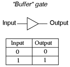
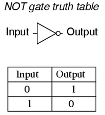
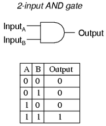
2. GATES
A single CMOS input/output is called a Logic Gate. Sometimes each gate has several inputs. A chip usually consists of several identical gates that can be used independently. In the datasheets we will find something called a Truth Table. It tells us how the logic gates operates. Lets take a look at a few different chips and their operations.

Buffer (CD4050)
This chip is rarely used in stompbox applications. But I wanted to use it as an example. As you can see by the Truth Table, if the input is high the output is high, and if the input is low the output is low. So this chip is simply a buffer (mostly used for interfacing to TLL logic).
Picture
Buffer schematic symbol and truth table
Inverter (CD4069/CD4049)
This chips, also sometimes called a NOT gate (or hex inverter because it has 6 gates), inverts the input. The output is 180 degress out of phase with the input. This is probably one of my favourite CMOS chips since they also can be configured as linear amplifiers. More about that later.

Notice the small circle at the output on the schematic symbol. This means that the gate is inverting. 
Picture
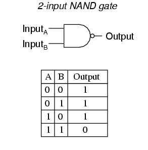
Now the logic gets alittle trickier...

AND GATE (CD4081)
This chip has four AND gates. Each gate has two inputs. With either or both inputs low, the output will be low; with both inputs high, the output will be high.

Both input A and input B needs to be high for the output to be high, hence the name "AND gate".
Picture
NAND gate (CD4011)
This is basically the same as a AND gate, except that it inverts the output. It can be useful when doing gated oscillators. I used a NAND schmitt trigger chip (the CD4093) for that application in my Flawed Logic Fuzz. We will breadboard a gated oscillator later on.

NAND stands for "NOT AND". Remember that a NOT gate is an inverter.
Picture

OR GATE (CD4071)
This chip has four OR gates. Each gate has two inputs. With either or both inputs high, the output will be high; With both inputs low, the output will be low.

Input A or Input B needs to be high for the output to be high, hence the name "OR gate".

NOR GATE (CD4001)
You can probably guess by now that the NOR gate (NOT OR) is an inverting OR gate, so I will not add the NOR gate schematic symbol and truth table.
Picture
NAND and NOR gate are sometimes called the universal gates, since they both can be used to form all the other basic logic gates.
Is it starting to make sense? Let have a look at a couple of more...

XOR GATE (CD4070)
This chip has four Exclusive OR gates. It also has two inputs per gate. It's a very versatile chip, because one of the inputs decides if the gate is inverting or non-inverting by tieing the input to either +V (non-inverting) or ground (inverting). In the Arcadiator I use this feature to make the alternating octaves - more on this later. This chip can also be used as a comparator as identical inputs gives a low output and different inputs gives a high output. So basically, if two different signals is put into the two inputs the output is the sum of the differences of those two (hence the name "exclusive or gate"). This is patrially how my ring mod The Corruptor works.
Picture

SCHMITT TRIGGER (CD40106)
Here's another very versatile chip. It's an inverter, but it has something called hysteresis built into the chip which makes it a schmitt trigger. Hysteresis is basically a "noise immunity zone". For example, if we use a 5 volt supply, the input signal will have to reach above 2.9 volts for the output to go low and it will have to drop down to belop 2.3 volts for the output to go high. That's a 0,6 volt hysteresis that will keep out any noise at the input that is below the threshold. The built in hysteresis also lets us configure this chip with diodes and resistors to do other logic funtions: multiple inputs NAND or NOR gates, pulse width modulation and much more.
Picture
Schmitt trigger schematic symbol

Those are a few basic CMOS chips. We'll use them later to breadboard stuff or analyze a few of my designs.

I mentioned before that not all CMOS chips follows this logic. We have many exceptions, switches, linear amplifiers, MOSFET cmos chips ect. I will cover a few of those later.

Lets stop there for a while. This post turned out alot bigger than I imagined and it can be a bit overwhelming! I had a hard time wrapping my head around this when I started out. If you are confused by the logic inputs and outputs, don't worry. In the next part we'll actually make something useful, a simple squarewave fuzz. The breadboard is a great learning platform, and by making a few small circuits I hope you will begin to understand these logic alittle better.

Please let me know what you think of this post and if you find anything that is incorrect.
/ Fredrik

Next part: CMOS workshop part 2
5 Comments
Anders
8/23/2015 05:31:52 pm

This is awesome! I've been curious about how these cmos circuits works. Thanks!

Reply
Fredrik Lyxzén link
8/23/2015 11:58:27 pm

Happy to hear that it's appreciated. Part 3 added today. :)

Reply
Jorge
2/24/2019 03:30:05 pm

Incredible series. As a seasoned musician and (almost) beginner in electronics, these articles are at perfect pace for me. Thanks a lot for taking the time to share your knowledge. Regards from Brazil.

Reply
Fredrik Lyxzén link
3/12/2019 03:16:30 am

I'm glad you like the CMOS series. :) Cheers

Reply
Virginia Teens link
3/13/2021 10:42:59 pm

Thank yyou for sharing

Reply


Leave a Reply.

  • DIY GUITAR EFFECTS
    • Original Effects
    • Building blog
    • DIY Gallery
    • Stripboard layouts
    • Articles
  • SHOP
  • BUILD DOCS
  • ABOUT